Substrate heat treatment apparatus
A technology for heat treatment device and substrate, which is applied in lighting and heating equipment, furnace components, furnace types, etc., can solve the problems that the temperature balance of the baking plate cannot be fully utilized, and the temperature treatment balance of the substrate cannot be improved, so as to achieve the effect of balanced heat treatment.
- Summary
- Abstract
- Description
- Claims
- Application Information
AI Technical Summary
Problems solved by technology
Method used
Image

Examples
Embodiment 1
[0041] Next, Embodiment 1 of the present invention will be described with reference to the drawings.
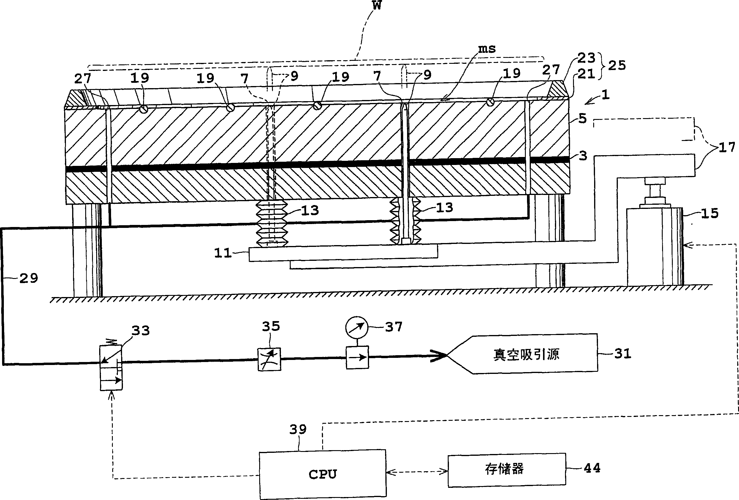
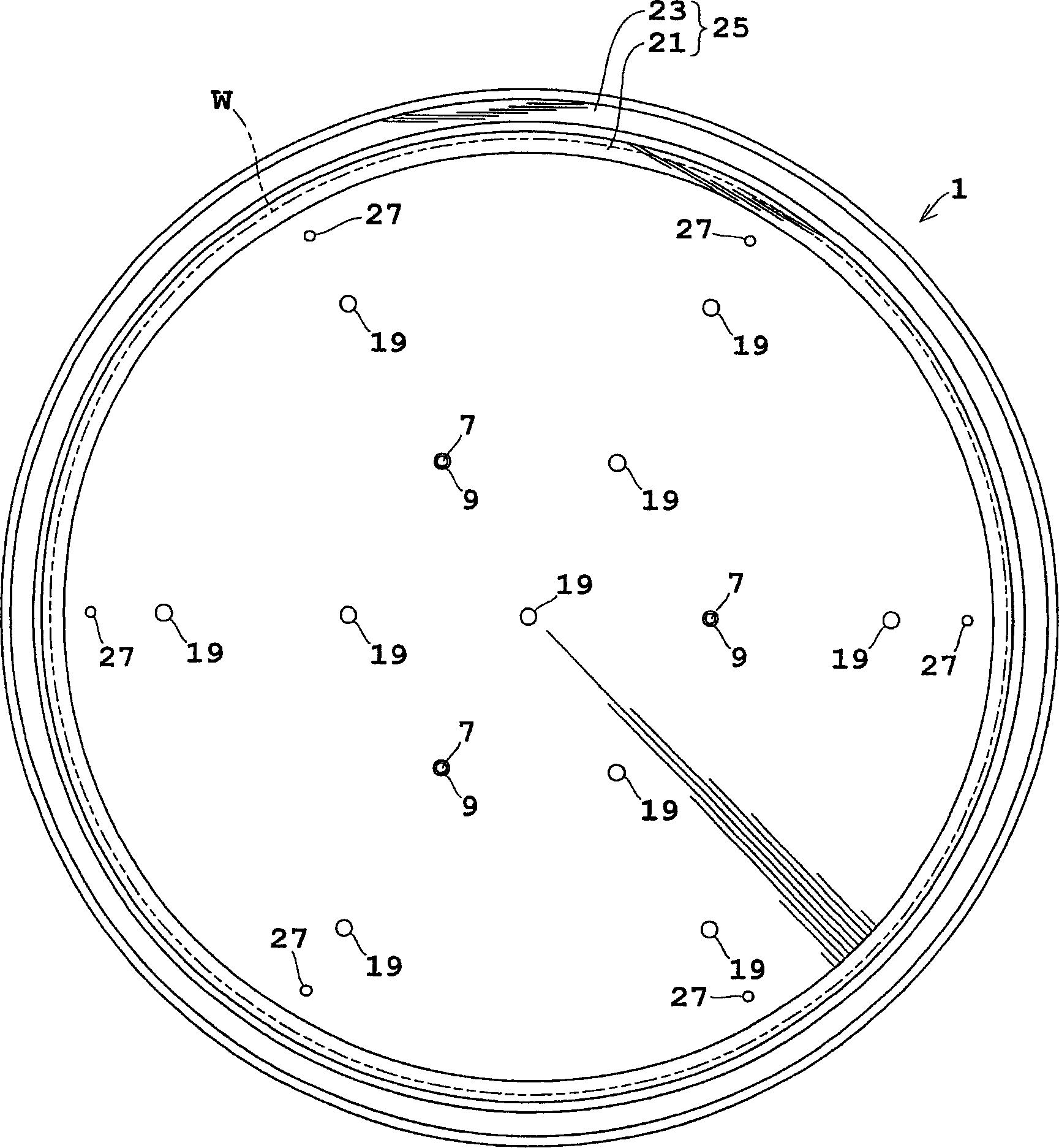
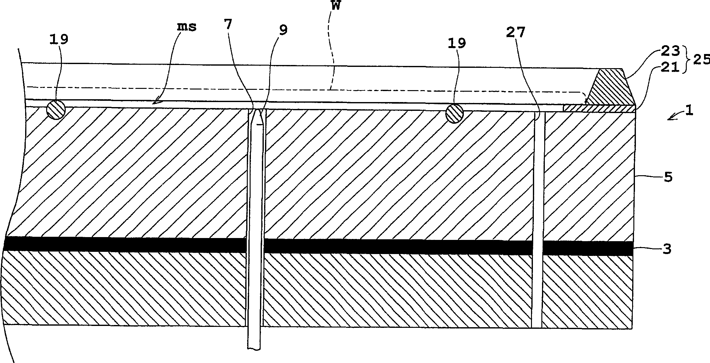
[0042] figure 1 It is a longitudinal sectional view showing a schematic structure of a substrate heat treatment apparatus according to Example 1, figure 2 yes figure 1 top view of image 3 It is an enlarged longitudinal sectional view of a baking plate.
[0043] A baking plate 1 with a substrate W is mounted on the upper surface, and a heating element 3 such as a mica heating element is attached to the lower portion. A plurality of heat transfer pipes (not shown) are buried in the heat transfer portion 5 between the heating element 3 and the upper surface of the baking plate 1 . In addition, a cooling tank (not shown) is formed between a plurality of heat transfer pipes (not shown), and a fluid for cooling flows.
[0044] Three through-holes 7 penetrating from the upper surface to the lower surface are formed in the baking plate 1 . These through-holes 7 are formed at ...
Embodiment 2
[0059] Next, Embodiment 2 of the present invention will be described with reference to the drawings. in addition, Figure 8 It is a vertical cross-sectional view showing a schematic configuration of a substrate heat treatment apparatus according to Example 2. In the following description, the same reference numerals are assigned to the same structures as those of the first embodiment described above, and detailed descriptions will be omitted.
[0060] This embodiment 2 is to further design the upper surface of the baking plate 1A.
[0061] That is, on the upper surface of baking plate 1A, more specifically, on the upper surface of heat transfer portion 5A, the inner side of sealing portion 25 is formed in a concave shape or a shallow mortar shape depressed toward the center. When there is a warp (valley warp) in which the central part of the substrate W protrudes downward from the peripheral part, the central part may be sucked first and the peripheral part may not be suffic...
Embodiment 3
[0063] Next, Embodiment 3 of the present invention will be described with reference to the drawings. in addition, Figure 9 It is an enlarged longitudinal sectional view showing a part of the substrate heat treatment apparatus according to the third embodiment. In addition, the same reference numerals are assigned to the same configurations as in the first embodiment described above, so that detailed descriptions will be omitted.
[0064] The structure of the closing portion 25A of this embodiment 3 is different from that of the foregoing embodiments 1 and 2.
[0065] That is, closing portion 25A has support portion 21A and restricting portion 23 , and support portion 21A is constituted by contact portion 43 and groove portion 45 . The contact portion 43 has an inner diameter slightly smaller than the outer diameter of the substrate W, and the upper surface of the contact portion 43 is in contact with the lower surface of the outer periphery of the substrate W on the inner s...
PUM
 Abstract
Description
Claims
Application Information
 - Generate Ideas
- Intellectual Property
- Life Sciences
- Materials
- Tech Scout
- Unparalleled Data Quality
- Higher Quality Content
- 60% Fewer Hallucinations
Browse by: Latest US Patents, China's latest patents, Technical Efficacy Thesaurus, Application Domain, Technology Topic, Popular Technical Reports.
© 2025 PatSnap. All rights reserved.Legal|Privacy policy|Modern Slavery Act Transparency Statement|Sitemap|About US| Contact US: help@patsnap.com