Heat exchanger and use thereof

A heat exchanger, heat transfer surface technology, applied in heat exchange equipment, heat exchanger types, indirect heat exchangers, etc., can solve problems such as plate-pin design and unit design limitations, inability to withstand long-term work, etc. Achieve the effect of compensating expenses and enhancing heat transfer

Inactive Publication Date: 2006-11-15
HIFLUX
View PDF7 Cites 11 Cited by
  • Summary
  • Abstract
  • Description
  • Claims
  • Application Information

AI Technical Summary

Problems solved by technology

[0011] In fact, due to its inability to withstand long-term work at high temperatures (typically higher than 650°C), more precisely,...

Method used


Image

  • Heat exchanger and use thereof
  • Heat exchanger and use thereof
  • Heat exchanger and use thereof

Examples


Embodiment Construction

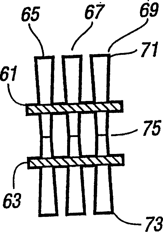
[0079] In the various embodiments described below, only two sets of plates are shown for convenience. However, it will be appreciated that in practice there will be a plurality of such plate sets.

[0080] figure 2 is a perspective view of a part of the core 1 of the recuperator according to the first embodiment of the invention. The core comprises a plurality of stacked or stacked pairs of plates, each pair of plates connected together by a pin passing through it. Such as figure 2 As shown, the partial stack comprises two plate pairs 3 , 5 . As shown in the upper part of the figure, the first board pair 3 includes an upper board 7 and a lower board 9 . The lower plate pair 5 also includes an upper plate 11 and a lower plate 13 .

[0081] In the core, all the plates are substantially planar (ie flat plates) and are arranged at a distance from each other, with their main planes spaced from each other in a parallel manner.

[0082] Accordingly, the plates 7 of the upper ...


PUM


Abstract

A heat exchanger comprises a plurality of plates (7, 9, 11, 13) each having first (15, 19) and second (17, 21) heat transfer surfaces on reverse sides. The plates are arranged in a stack with spacings between mutually facing heat transfer surfaces of adjacent plates. Alternate spacings in the stack providing respectively, a first fluid path (51, 52) for a first fluid and a second fluid path (57, 59) for a second fluid. The plates are arranged in a plurality of groups, each comprising at least two plates. Pin means are provided in the form of a plurality of groups of pins (23). The pins of each pin group are arranged to bridge plates of a respective plate group.

Description

technical field [0001] The present invention relates to heat exchangers (or heat exchangers) and their use in various industrial applications. A variety of such applications will be described in more detail below, but use in gas turbine construction constitutes a preferred class of implementation. Background technique [0002] Gas turbines are commonly used in distributed power generation and power transmission. In these and other applications, there are many problems in providing suitable heat exchangers (recuperators) that perform well and are of suitable size, cost and performance. [0003] For air-to-air heat exchangers, a plate-fin or tube-sheet configuration is usually ideal. A traditional tube-sheet heat exchanger consists of a structure in which a fluid flows through a length of tubes that run through a stack of parallel plates. A second fluid flows in the gaps between the plates. [0004] US-A-5 845 399 discloses a carbon fiber composite heat exchanger in which ...

Claims


Application Information

Patent Timeline
IPC IPC(8): F28F3/02F28D9/00
Inventor 坦齐·贝赞特约翰·科普林阿尔贝·德马尔涅阿诺德·詹姆斯·斯图尔特·普拉特
Owner HIFLUX
Why Eureka
Try Eureka