Removing method of gear-hobbing burr

A burr and gear hobbing technology, applied in the direction of components with teeth, gear teeth, belts/chains/gears, etc., can solve the problem of difficult removal of burrs, and reduce the process of dehairing by fitters or dehairing the end face of lathes. , the effect of reducing production costs and improving production efficiency

Inactive Publication Date: 2006-11-29
GUIZHOU QUNJIAN PRECISION MACHINERY
View PDF0 Cites 8 Cited by
  • Summary
  • Abstract
  • Description
  • Claims
  • Application Information

AI Technical Summary

Problems solved by technology

[0006] 2) Burrs are difficult to remove
But this method also has obvious shortcomings: the car removes the burr on the end face of the gear, but makes the burr turn into the tooth groove

Method used


Image

  • Removing method of gear-hobbing burr
  • Removing method of gear-hobbing burr
  • Removing method of gear-hobbing burr

Examples


Embodiment Construction

[0021] Embodiments of the present invention: take machining shaft gear as example, it comprises the following steps:

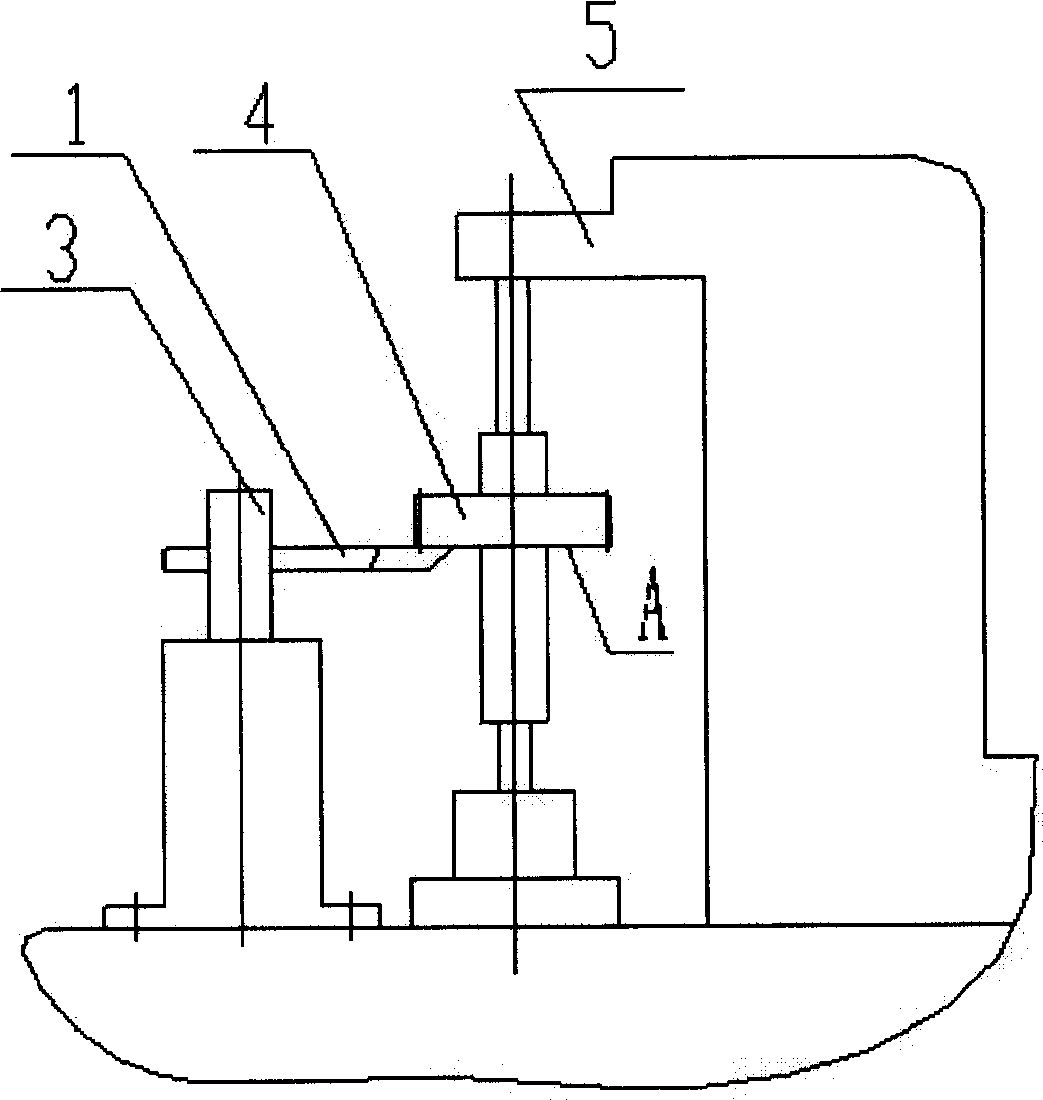
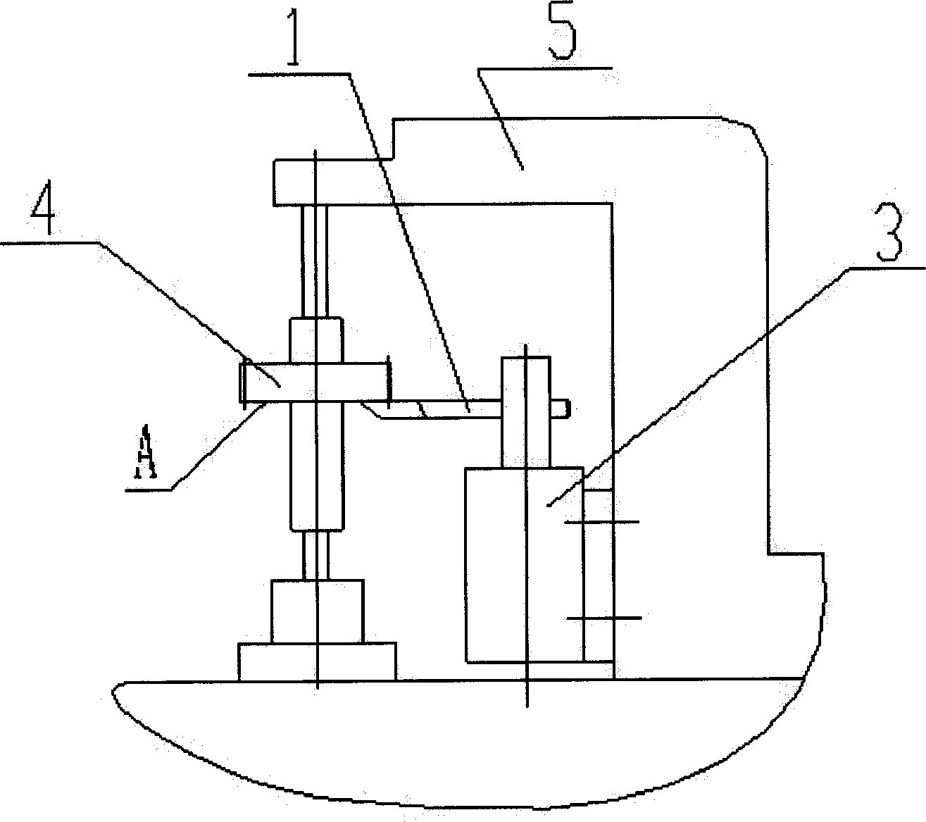
[0022] First, the gear shaft blank 4 to be processed is clamped on the gear hobbing machine 5, and the positioning is adjusted;

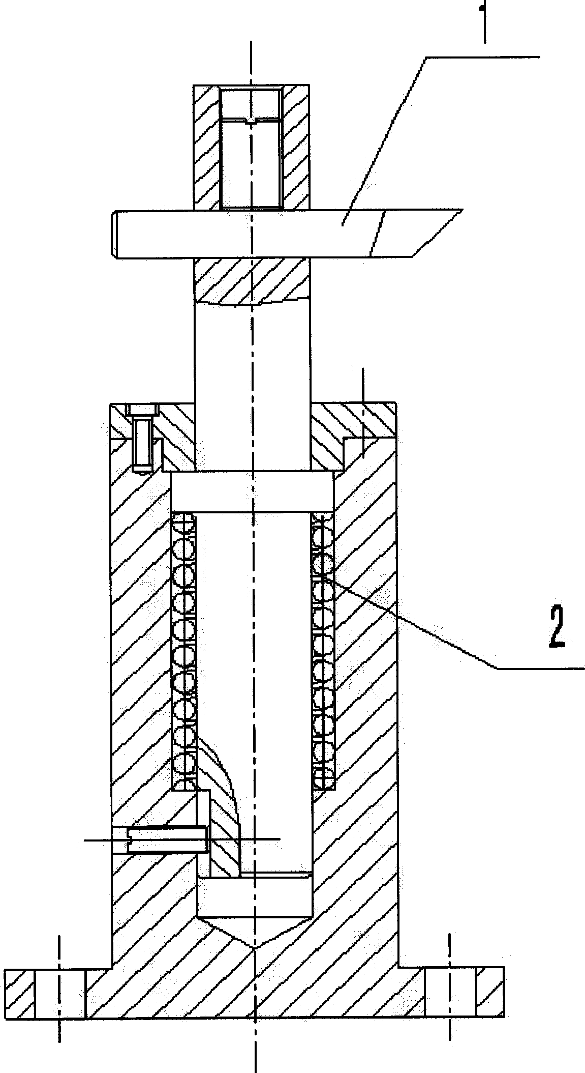
[0023] The second, the special-purpose elastic knife rest 3 that has depilator 1 is installed on the base of gear hobbing machine 5, as figure 2 shown; or the special elastic knife rest 3 with the depilatory knife 1 is installed on the small column of the gear hobbing machine 5, as image 3 As shown; adjust the position of the deburring knife 1, first make the deburring knife 1 slightly exceed the design position of the tooth root in the horizontal direction, and slightly higher than the cutting surface of the workpiece in the vertical direction, that is, the A surface, and then press down on the deburring knife 1 , so that the dehairing knife 1 is closely attached to the cutting surface A of the workpiece under the action of the ...


PUM


Abstract

A method for removing the burr form the hobbed gear includes such steps as fixing the workpiece to be hobbed to the hobbing machine, locating it, installing an elastic carrier of the burr removing cutter onto said hobbing machine, regulating the position of burr removing cutter to make it close to the surface of said workpiece and hobbing while removing burr.

Description

Technical field: [0001] The invention relates to a method for removing hobbing burrs in gear processing. Background technique: [0002] Gears are important basic parts in mechanical products. Hobbing is the most common machining method for spur and helical involute spur gears. When hobbing, in the direction of the hob, the end face of the gear often inevitably produces hobbing burrs. [0003] For hobbing burrs, they must be removed. Because the burr will directly affect the working accuracy and product performance of the gear. Especially for those gears that have clear and high requirements for meshing noise, the hobbing burrs must be completely removed, otherwise the meshing noise index is difficult to meet the use requirements. [0004] At present, most manufacturers use the method of fitter to remove hair. This approach has very obvious disadvantages: [0005] 1) The labor intensity is very large and the work efficiency is very low. The fitter needs to use a file o...

Claims


Application Information

Patent Timeline
Patent Type & Authority Applications(China)
IPC IPC(8): B23F19/00
Inventor 石年平
Owner GUIZHOU QUNJIAN PRECISION MACHINERY
Why Eureka
Try Eureka