Small pump

A technology of small pumps and pump chambers, applied in the direction of pumps, pumps with flexible working elements, liquid displacement machinery, etc., can solve the problems of air leakage, function reduction, pressurization time, etc., and achieve noise prevention and high-efficiency valves The role of the valve, the effect of realizing the role of the valve

Inactive Publication Date: 2006-11-29
MITSUMI ELECTRIC CO LTD
View PDF1 Cites 4 Cited by
  • Summary
  • Abstract
  • Description
  • Claims
  • Application Information

AI Technical Summary

Problems solved by technology

Furthermore, in order to eliminate this noise, it is also considered to form a rough pockmark on the diaphr...

Method used


Image

  • Small pump
  • Small pump
  • Small pump

Examples


Embodiment

[0041] Below, according to Figure 1 to Figure 10 An embodiment of the present invention will be described.

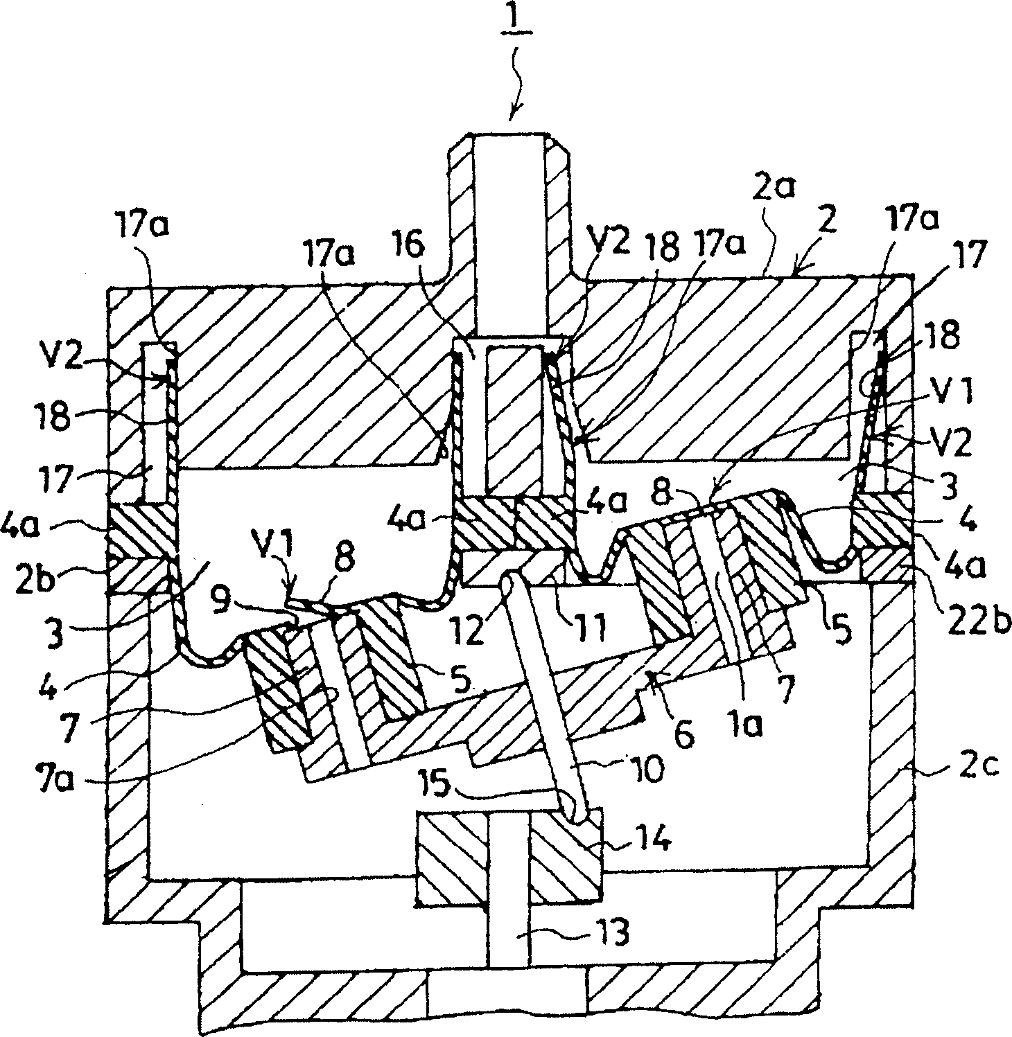
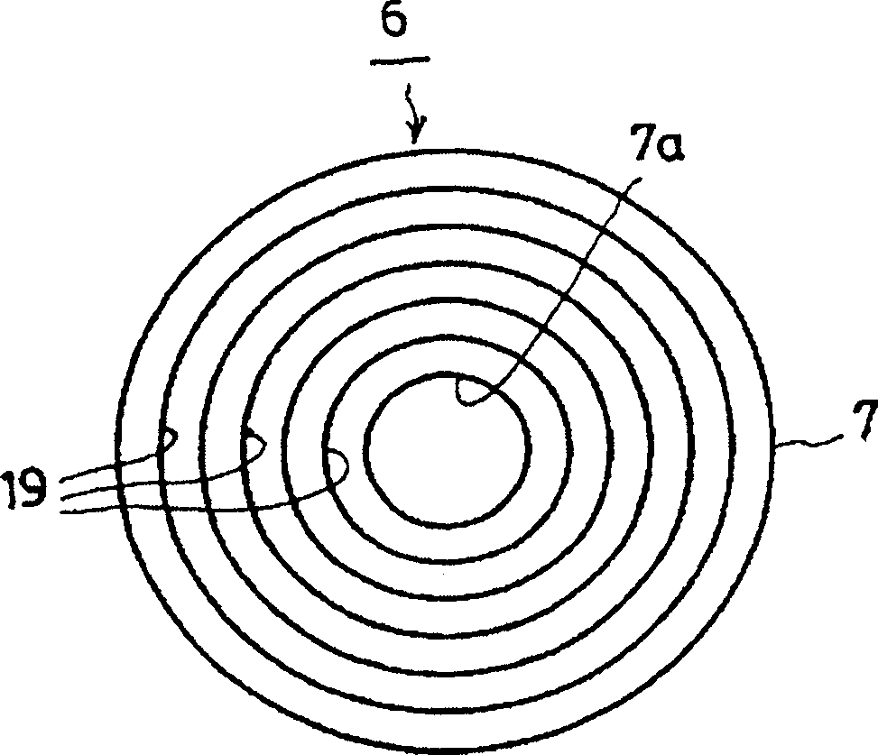
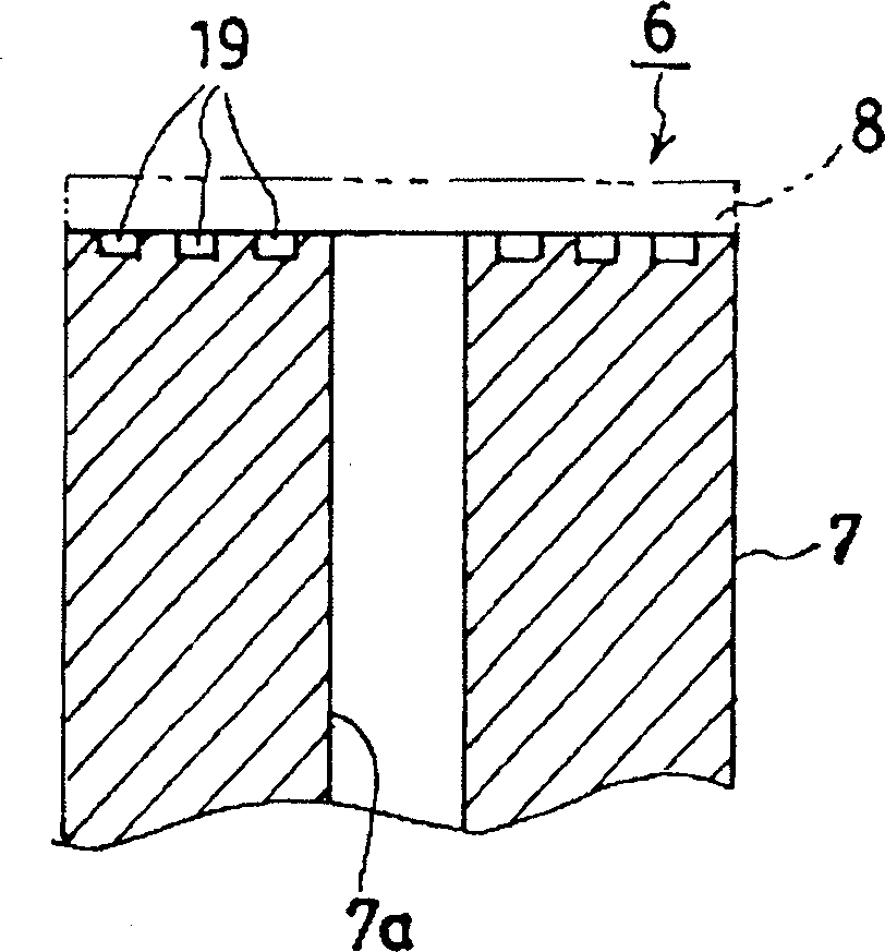
[0042] figure 1It is a vertical sectional view of a small pump. In this small pump 1, diaphragms 4, 4 forming pump chambers 3, 3 are provided in a rectangular housing 2 viewed from above. Hollow mounting bodies 5, 5 protrude downward, and oscillating bodies 6 for moving the lower surfaces of the diaphragms 4, 4 up and down are provided below the diaphragms 4, 4.

[0043] In addition, the casing 2 is made into three sections: an upper casing 2a, a middle casing 2b, and a lower casing 2c. In the diaphragms 4, 4, the flanges 4a, 4a... of the diaphragms 4, 4 are It is sandwiched between the above-mentioned upper case 2 a and the above-mentioned middle case 2 b and held by the case 22 .

[0044] Furthermore, on the oscillating body 6, in the vicinity of the periphery of the oscillating body 6, and below the central parts of the respective diaphragms 4, 4, an upwardly pro...


PUM


Abstract

The objective is to prevent noise of a small pump and improve performance of the small pump. Recess grooves 19, 19..., 20, 20..., 21, 21... or hollows 22, 22..., 23, 23... are scored on an intake valve element 8 opening and closing an intake valve part V1 of the small pump 1 or an upper surface of a rocking body 6 pressed against a back surface of the intake valve element to reduce contact area of the intake valve element 8 and the upper surface of the rocking body 6. Consequently, adhesion of the intake valve body 8 and the rocking body 6 is prevented to reduce noise at a time of open and close of the intake valve element 8.

Description

technical field [0001] The present invention relates to a small pump used in a sphygmomanometer and the like, and particularly relates to a small pump in which noise is prevented. Background technique [0002] In the existing small-sized pump, a pump chamber is formed in the housing, and the pump chamber is formed by a plurality of diaphragms, and each diaphragm is connected to each other as a whole. In addition, an oscillating body for moving the lower surface of the diaphragm up and down is provided under the diaphragm. [0003] Furthermore, a through hole is opened in the central part of the lower surface of the diaphragm respectively, and the suction valve body with the through hole is formed integrally with the lower surface of the diaphragm. On the other hand, the respective diaphragms are fixed to the oscillating body while an air introduction hole communicating with the through hole of the diaphragm is opened near the periphery of the oscillating body. In addition,...

Claims


Application Information

Patent Timeline
IPC IPC(8): F04B45/04
Inventor 山川宗春
Owner MITSUMI ELECTRIC CO LTD
Why Eureka
Try Eureka