Temp. compensation device of electronic signal

A technology of temperature compensation device and electronic signal, applied in the direction of using electric devices, thermometers, thermometers using electric/magnetic components directly sensitive to heat, etc. standards and other issues

Inactive Publication Date: 2006-11-29
FORTUNE SEMICON
View PDF0 Cites 12 Cited by
  • Summary
  • Abstract
  • Description
  • Claims
  • Application Information

AI Technical Summary

Problems solved by technology

Although this analog temperature compensation technology has the characteristics of low cost, when performing calibration and compensation, the temperature of the reference voltage source as one of the signals will drift, which will affect the output results of calibration and compensation, resulting in calibration accuracy not allowed
In order to overcome the temperature drift, there are two methods. The first method focuses on the circuit design of the reference voltage source or the design of the parameters and structure of the semiconductor manufacturing process. The temperature coefficient of the reference voltage source is as close to zero as possible. This method not only complicates the circuit design, but also cannot completely eliminate the temperature drift caused by the influence of the outside world on the reference voltage source. In addition, for converters with different circuit designs or applications, the reference voltage source circuit must be differently adjusted. design, which will increase R&D costs; the second method uses general standard semiconductor process technology

Method used


Image

  • Temp. compensation device of electronic signal
  • Temp. compensation device of electronic signal
  • Temp. compensation device of electronic signal

Examples


Embodiment Construction

[0023] Hereinafter, the present invention will be described in detail with reference to the accompanying drawings.

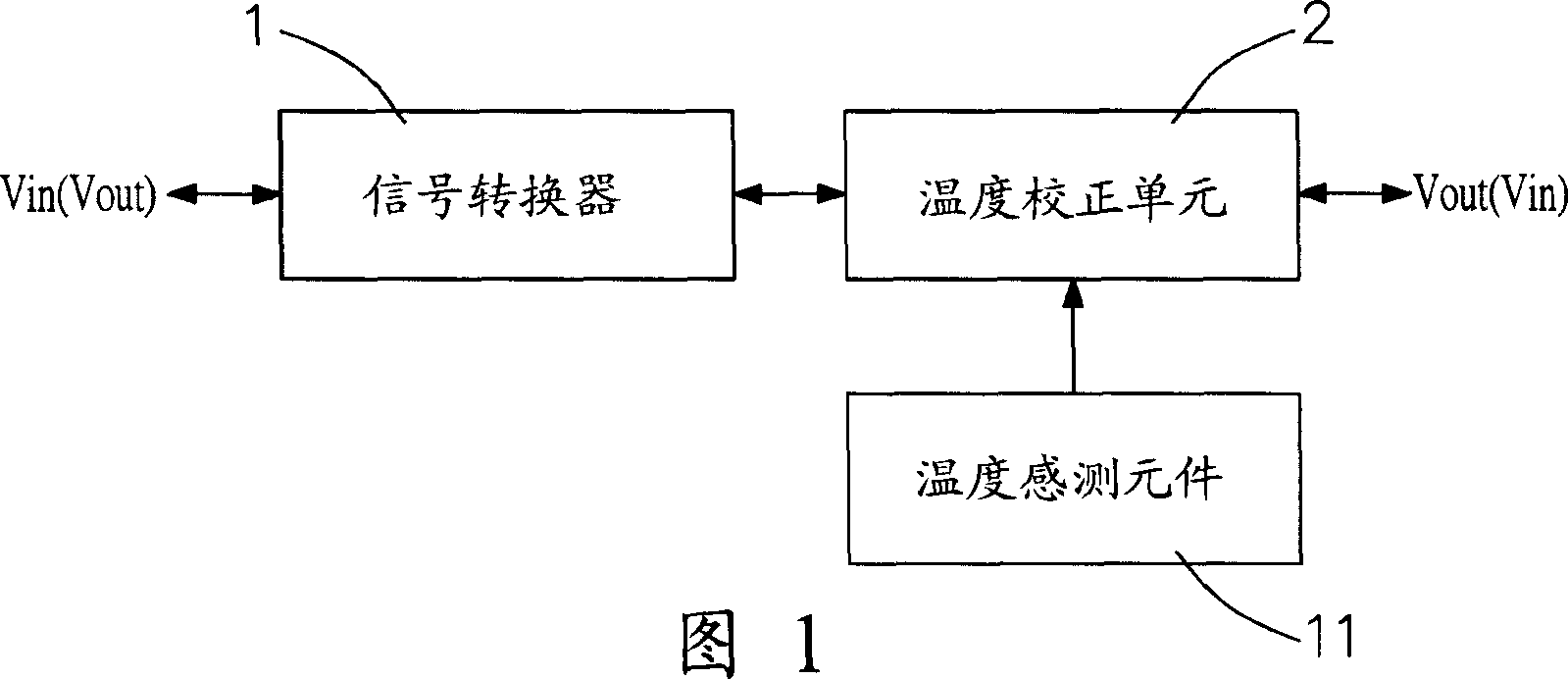
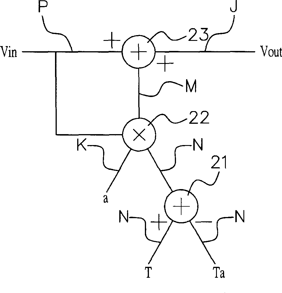
[0024] Figure 1 and figure 2 They are respectively a structural block diagram and a circuit structural diagram of an electronic signal temperature compensation device according to an embodiment of the present invention. As shown in the figure, the electronic signal temperature compensation device of the present invention includes: a signal converter 1 and a temperature correction unit 2 coupled to the signal converter 1 for temperature correction and compensation. One end of the signal converter 1 is the input end for coupling the obtained input signal Vin, the other end is coupled to the input end of the temperature correction unit 2, the other end of the temperature correction unit 2 is the signal output end Vout, and the input signal is in the digital When converting between analog and analog, the temperature compensation device performs temperature correcti...


PUM


Abstract

The invention is a temperature compensator for electronic signal, comprising: signal converter, and temperature correction unit coupled with the signal converter to make temperature correction and compensation, where the temperature correction unit comprises a digital circuit composed of first adder, first multiplier and second adder, executing temperature correction and compensation digital calculation according to the measured real-time environmental temperature value, reference temperature, temperature compensation coefficient and input signal and then producing corrected signal output, thus solving the problems of influence and low accuracy caused by temperature drift of reference voltage source of analog compensation technique.

Description

technical field [0001] The invention relates to a temperature compensation device for electronic signals, in particular to a temperature correction and compensation device suitable for input and output of electronic signals such as infrared rays, chips, temperature sensing and control, voltage sources, and current sources. Background technique [0002] With the development of electronic industry technology, not only electronic products have become more refined, but also the accuracy requirements for the transmission of electronic signals have been relatively increased, that is, it is required that electronic signals will not be affected by external force majeure factors such as the environment during the transmission process ( Such as temperature changes, etc.) cause wrong judgment of the signal. Therefore, in various current electronic components or products, temperature compensation devices are used to automatically or manually correct and compensate the signal so that it i...

Claims


Application Information

Patent Timeline
Patent Type & Authority Applications(China)
IPC IPC(8): G01J5/00G01J5/16G01K7/00G01K7/12G05D23/19G05F1/567
Inventor 黄一洲
Owner FORTUNE SEMICON
Why Eureka
Try Eureka