Multifrequency antenna
A multi-frequency antenna and antenna technology, applied to the antenna, the device that enables the antenna to work in different bands at the same time, the structural form of the radiation element, etc., to achieve the effect of reducing the installation space
- Summary
- Abstract
- Description
- Claims
- Application Information
AI Technical Summary
Problems solved by technology
Method used
Image

Examples
Embodiment Construction
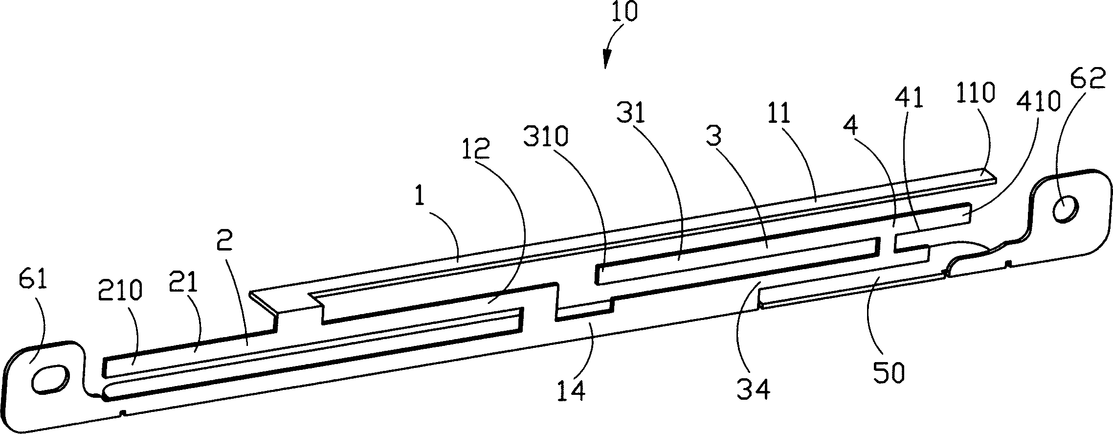
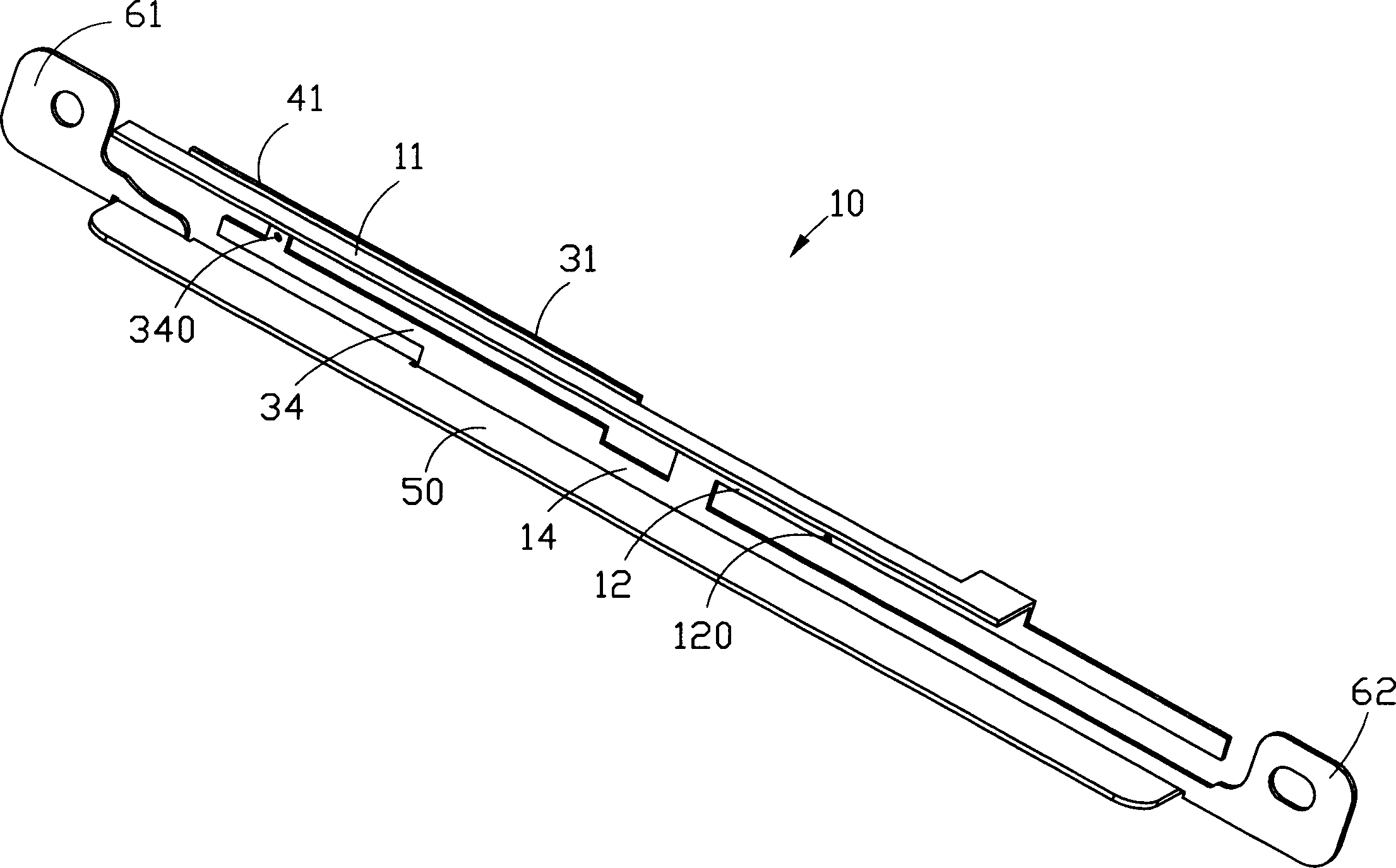
[0012] Please refer to figure 1 and figure 2 , which is a perspective view of a multi-frequency antenna provided according to a preferred embodiment of the present invention. The multi-frequency antenna 10 includes a first antenna 1 and a second antenna 2 for a wireless wide area network, and a third antenna 3 and a fourth antenna 4 for a wireless local area network. The multi-frequency antenna 10 is made by stamping a metal sheet, and combines the wireless wide area network antenna and the wireless local area network antenna together.
[0013] Both ends of the multi-frequency antenna 10 have a first mounting portion 61 and a second mounting portion 62 , and the first mounting portion 61 and the second mounting portion 62 form a mounting plane. The multi-band antenna 10 includes a ground portion 50 , which is a common ground portion for the first antenna 1 , the second antenna 2 , the third antenna 3 and the fourth antenna 4 . A bending portion 14 extends vertically upward...
PUM
 Abstract
Description
Claims
Application Information