Supercharge Your Innovation With Domain-Expert AI Agents!

Electronic element automatic moving loader

A technology of electronic components and transfer devices, applied in the direction of measuring devices, measuring electricity, measuring electrical variables, etc., can solve problems such as deviation from the initial position, inability to adsorb electronic components, transfer and pick-and-place actions, etc.

Inactive Publication Date: 2010-10-06
YAMAHA MOTOR CO LTD
View PDF8 Cites 0 Cited by
  • Summary
  • Abstract
  • Description
  • Claims
  • Application Information

AI Technical Summary

Problems solved by technology

[0010] And, for Japanese Utility Model Publication No. 2544015, Japanese Patent Publication No. 2002-148303, Japanese Patent Publication No. Hei 11-333775, there are parts heated by the heater ( When the positions of inspection sockets, suction nozzles, and heating plates) deviate from the initial positions due to thermal expansion
After the position of the above-mentioned components is displaced due to thermal expansion, it is impossible to use the suction nozzle to accurately pick up and place electronic components such as suction, transfer, and loading into the socket for inspection.

Method used


Image

  • Electronic element automatic moving loader
  • Electronic element automatic moving loader
  • Electronic element automatic moving loader

Examples


Embodiment Construction

[0051] Below, combine Figure 1 to Figure 22 An embodiment of the electronic component automatic transfer device in the present invention will be described in detail.

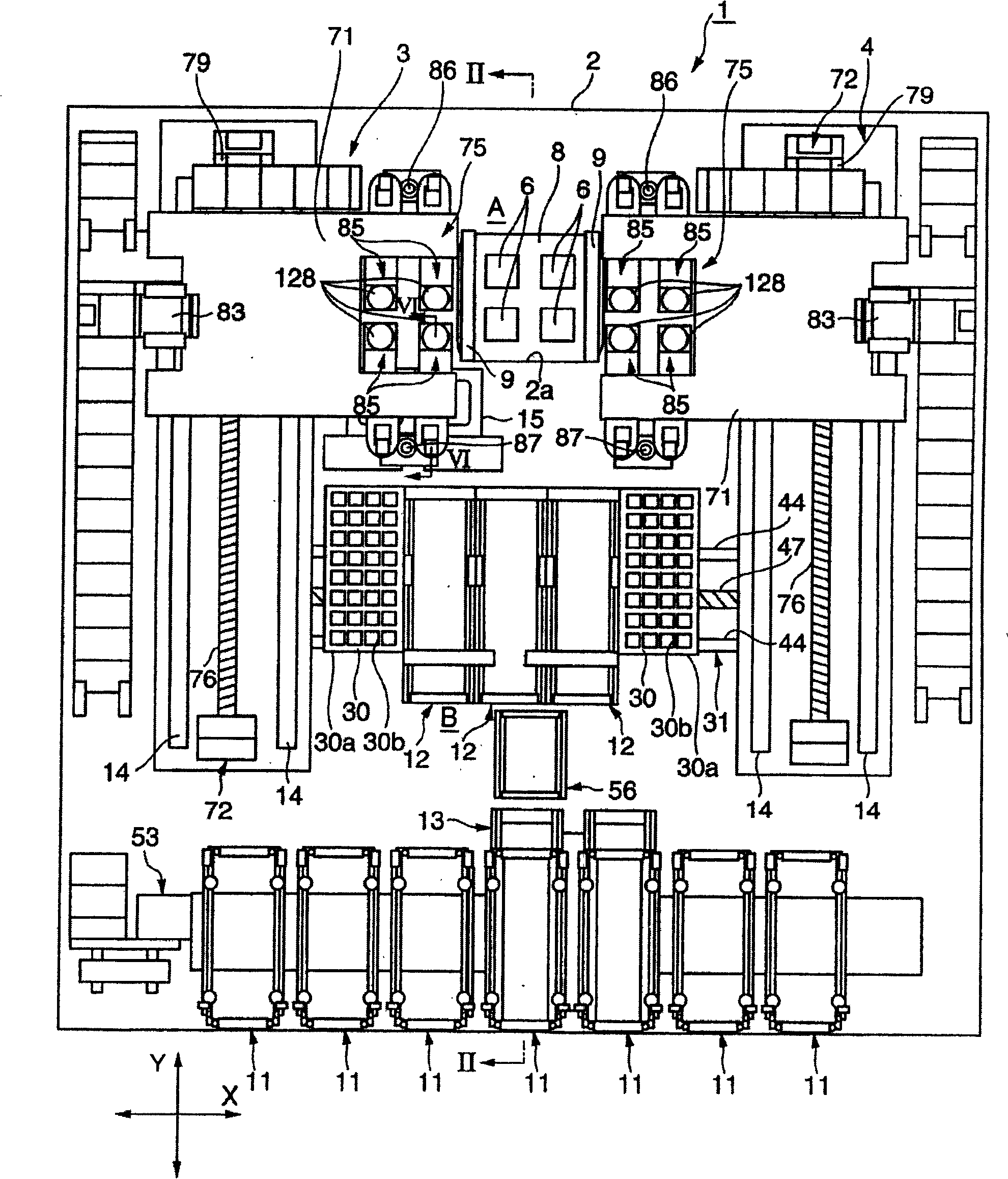
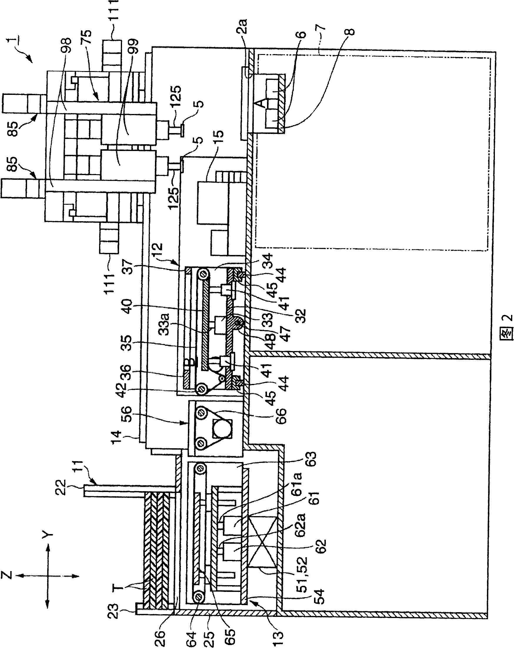
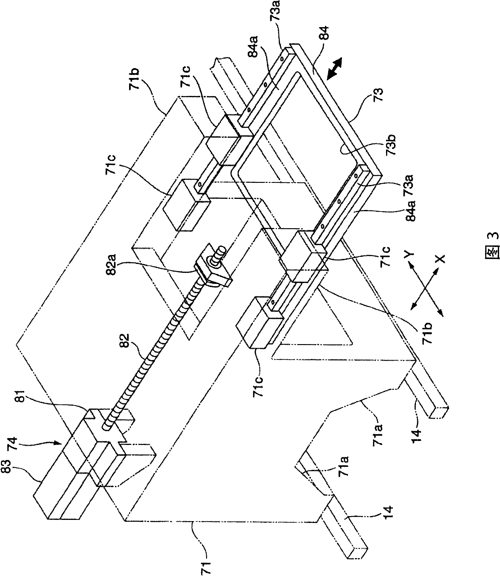
[0052] figure 1 It is a plan view of the electronic component automatic transfer device in the present invention. In this figure, a pallet support device and a stocker are depicted without a pallet placed above. figure 2 yes figure 1 The II-II line profile, image 3 is a perspective view illustrating the structure of the component moving device, Figure 4 is a perspective view of the head unit, Figure 5 is a perspective view illustrating the direction of movement of the unit cells, and only two unit cells are depicted in this figure. Image 6 Is a side view of a unit cell, broken to show the connected parts of the structural components. figure 1 The cutting position is shown by line VI-VI in . Figure 7 It is a sectional view showing the suction nozzle part enlarged.

[0053] Figure 8 It is a struc...


PUM


Abstract

The invention relates to an automatic moving and loading device for electronic component, comprising: suction nozzle sucking electronic component; heater heating sucked electronic component; sucking head lifting said suction nozzle; head unit supporting suction head; component moving device moving said head unit between component loading part and checking plug seat; said suction head including lift part lifting in relative to head unit and rotation part rotating surrounding up-and-down axis in relative to lift part. Said suction nozzle and rotation part rotates together. Said heater is installed on said lift part, and is corresponding to said rotation part through fluid and heat conductive filling material. The invention is characterized in that the suction nozzle rotates under condition of not causing wind and breakage of heater cable.

Description

technical field [0001] The present invention relates to a so-called automatic electronic component transfer device that takes out components stored in a tray or the like through a movable suction head and loads them into sockets for inspection in order to perform predetermined inspections. Background technique [0002] As the above-mentioned automatic transfer device for electronic components, in the past, for example, there are structures such as those disclosed in Japanese Utility Model Publication No. 2544015 or Japanese Patent Publication No. 2002-148303, in which electronic components are heated to a predetermined temperature and loaded into the socket for inspection The product. The above-mentioned Japanese utility model patent publication No. 2544015 or the electronic component automatic transfer device shown in Japanese Patent Publication No. 2002-148303 utilizes the suction nozzle adsorption element arranged at the lower end of the suction head, which includes heati...

Claims


Application Information

Patent Timeline
Patent Type & Authority Patents(China)
IPC IPC(8): G01R31/26G01R31/00
Inventor 菅野幸男福川义章
Owner YAMAHA MOTOR CO LTD
Features
  • R&D
  • Intellectual Property
  • Life Sciences
  • Materials
  • Tech Scout
  • Unparalleled Data Quality
  • Higher Quality Content
  • 60% Fewer Hallucinations
Learn More