Supercharge Your Innovation With Domain-Expert AI Agents!

Power transmission device

A power transmission device and power transmission technology, applied in the direction of transmission, gear transmission, transmission control, etc., can solve the problem of unable to drive the power transmission of the wheel to the internal combustion engine, etc.

Active Publication Date: 2015-12-30
HONDA MOTOR CO LTD
View PDF6 Cites 2 Cited by
  • Summary
  • Abstract
  • Description
  • Claims
  • Application Information

AI Technical Summary

Problems solved by technology

[0004] In addition, in such continuously variable transmissions, the power transmission from the output shaft to the external parts is blocked by the one-way clutch, so the power of the drive wheels cannot be transmitted to the internal combustion engine, and the power of the drive wheels cannot be used to start the internal combustion engine

Method used


Image

  • Power transmission device
  • Power transmission device
  • Power transmission device

Examples


Embodiment Construction

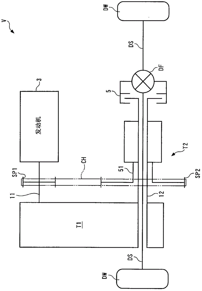
[0155] Hereinafter, preferred embodiments of the present invention will be described in detail with reference to the drawings. figure 1 The shown internal combustion engine (hereinafter referred to as "engine") 3 is a gasoline engine mounted as a power source in vehicle V, and its fuel injection valve (hereinafter referred to as "injector") 3a performs a fuel injection operation, a spark plug (not shown) The ignition action performed by the diagram) is controlled by ECU2 described later (refer to Figure 9 ).

[0156] Such as figure 1 As shown, the power transmission device according to the first embodiment of the present invention transmits power between the engine 3 and the drive wheels DW, DW of the vehicle V, and has a first transmission T1 and a second transmission T2 arranged in parallel with each other.

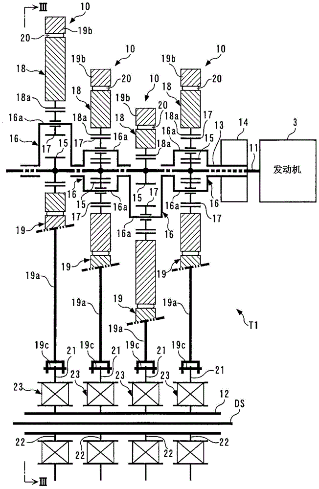
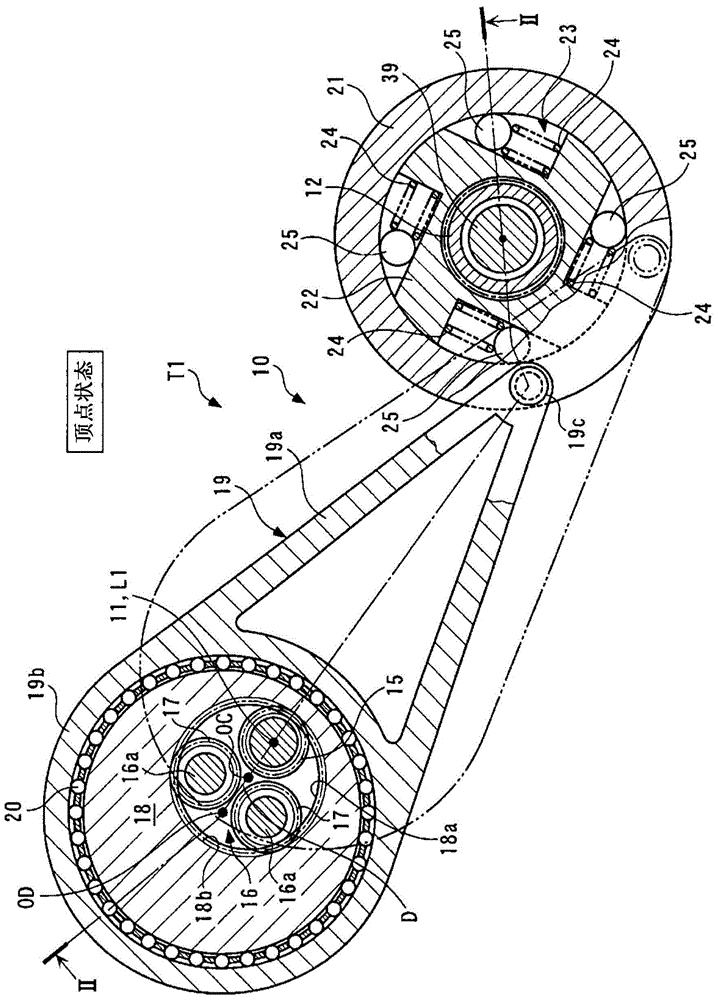
[0157] The first transmission T1 is a continuously variable transmission applying the principle of a four-joint link, and continuously changes the power of the eng...


PUM


Abstract

Provided is a power transmission device that can appropriately apply engine braking to drive wheels while a vehicle is decelerating, and can thereby improve drivability and prevent overspeeding of an internal combustion engine. The power transmission device is provided with a first gearshift device for gearshifting the power of the internal combustion engine in a stepless manner and transmitting the power to drive wheels of the vehicle, and a second gearshift device (T2) for gearshifting the power in a stepwise manner and transmitting the power between the internal combustion engine and the drive wheels, the second gearshift device being provided in parallel with the first gearshift device. The second gearshift device (T2) has: first rotating elements (62, 72) linked to the internal combustion engine, second rotating elements (65, 73) linked to the drive wheels, a third rotating element (63), and a fourth rotating element (76), the rotational speeds of the rotating elements being in a mutually collinear relationship; power-transmission-varying devices (81, 111) capable of varying the power transmitted between the first rotating elements (62, 72) and the internal combustion engine; a first brake (91) for braking the third rotating element (63); and a second brake (101) for braking the fourth rotating element (76).

Description

technical field [0001] The present invention relates to a power transmission device for transmitting power between an internal combustion engine and drive wheels of a vehicle. Background technique [0002] Conventionally, as such a power transmission device, for example, a power transmission device disclosed in Patent Document 1 is known. The power transmission device has a continuously variable transmission applying the so-called four-link principle. The continuously variable transmission has: an input shaft and an output shaft respectively coupled to a crankshaft of an internal combustion engine and a driving wheel of a vehicle; an eccentric disc and an outer member respectively coupled to the input shaft and the output shaft; a coupling coupling the eccentric disc and the outer member to each other. a rod; and a one-way clutch disposed between the output shaft and the external component. The eccentric disk is configured such that the amount of eccentricity with respect ...

Claims


Application Information

Patent Timeline
Patent Type & Authority Applications(China)
IPC IPC(8): F16H37/02F16H21/20F16H29/04F16H31/00F16H61/12F16H3/66
CPCF16H29/04F16H61/21
Inventor 市川和树小林庸浩吉野文博
Owner HONDA MOTOR CO LTD
Features
  • R&D
  • Intellectual Property
  • Life Sciences
  • Materials
  • Tech Scout
  • Unparalleled Data Quality
  • Higher Quality Content
  • 60% Fewer Hallucinations
Learn More