Electronic device with floating type MIC

An electronic device, floating technology, applied in frequency/direction characteristic device, electrical equipment shell/cabinet/drawer, electrical components and other directions, can solve the problem of poor microphone radio effect, fixed position, poor frequency resonance, etc. Achieve the effect of improving the sound quality, increasing the resonance effect, and increasing the practicability.

Active Publication Date: 2006-12-20
ASUSTEK COMPUTER INC
View PDF0 Cites 1 Cited by
  • Summary
  • Abstract
  • Description
  • Claims
  • Application Information

AI Technical Summary

Problems solved by technology

[0005] However, the traditional acoustic holes are arranged on the casing in the form of openings, and their positions are fixed.
If the opening position of the sound receiving hole is poorly designed, it will directly affect the sound receiving effect of the microphone
[0006] In addition, due to the small size of the radio mechanism, only a small radio space can be used
In this way, the frequency resonance effect of the sound will be poor, and the microphone's sound collection effect will be poor
[0007] In addition, in order to solve the problem of poor frequency resonance, some manufacturers use microphones with higher power, but the volume of microphones with higher power is also larger.
Therefore, the radio space of the electronic device is quite occupied, and the production cost is increased

Method used


Image

  • Electronic device with floating type MIC
  • Electronic device with floating type MIC
  • Electronic device with floating type MIC

Examples


Embodiment Construction

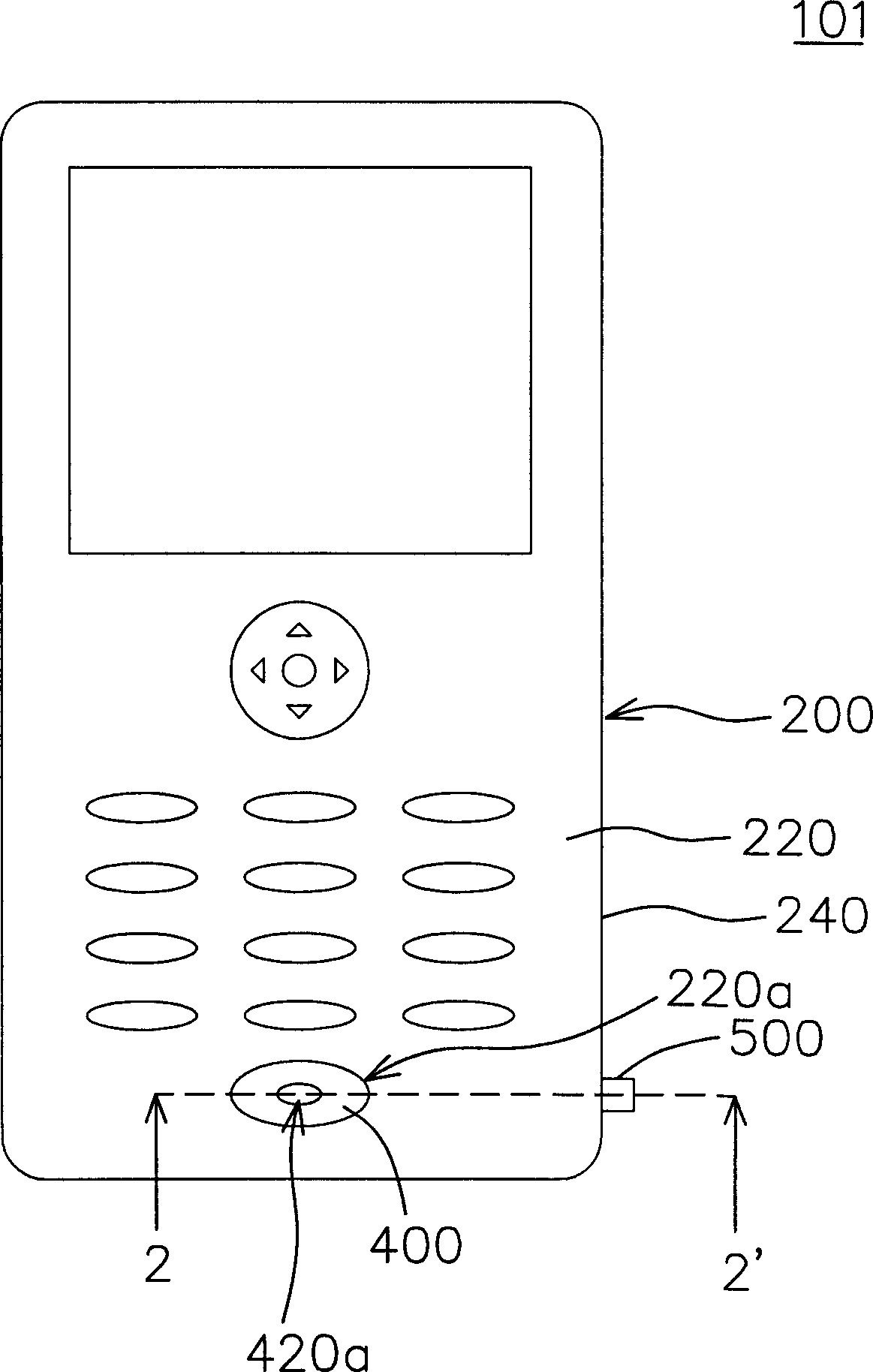
[0028] Please also refer to Figure 1~2 , figure 1 A schematic diagram illustrating an electronic device with a floating acoustic hole according to an embodiment of the present invention, figure 2 drawn along figure 1 An enlarged cross-sectional view of a portion of the electronic device viewed on section line 2-2'. The electronic device 101 of this embodiment may include portable electronic devices such as a mobile phone, a personal digital assistant, or a digital recording device. Here, the structure of the electronic device 101 of this embodiment will be described using a mobile phone as an example.

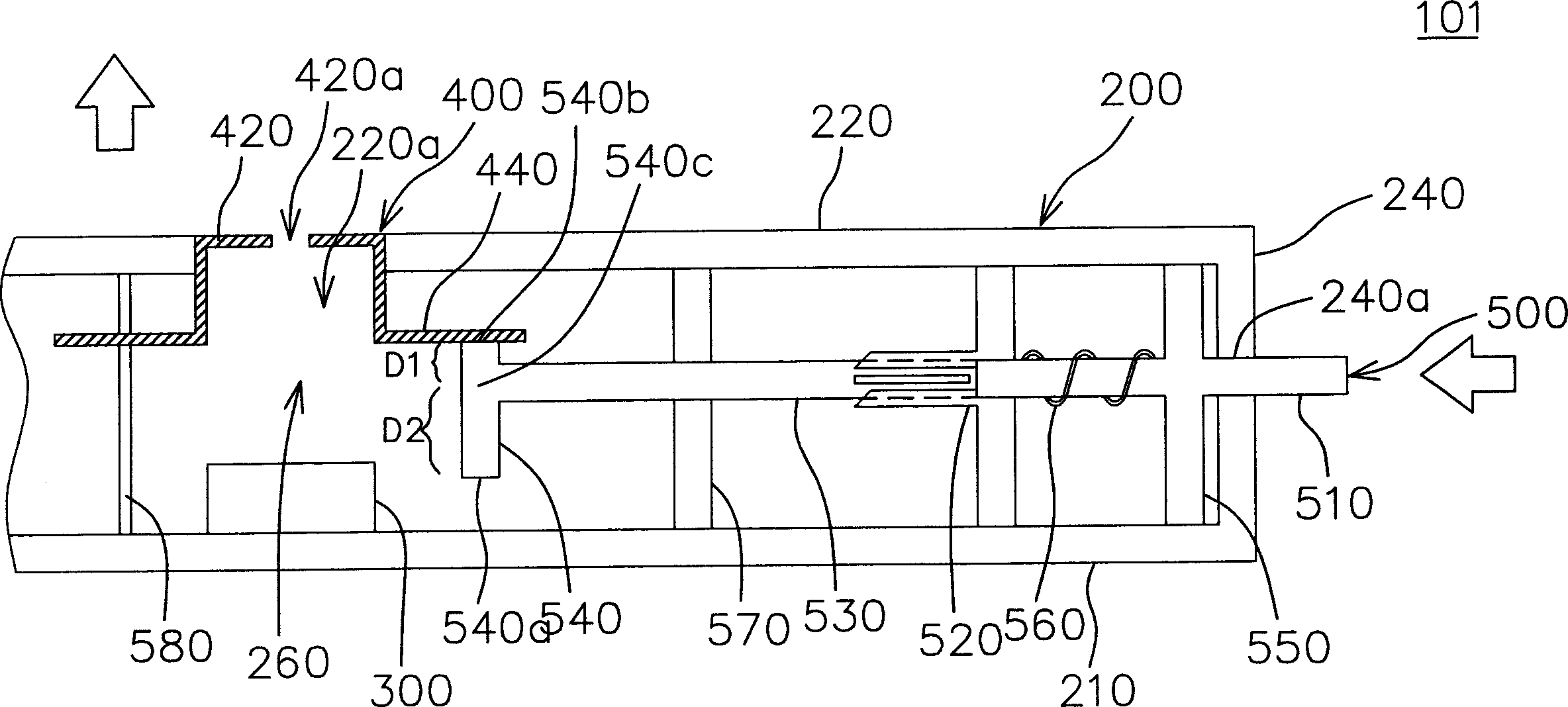
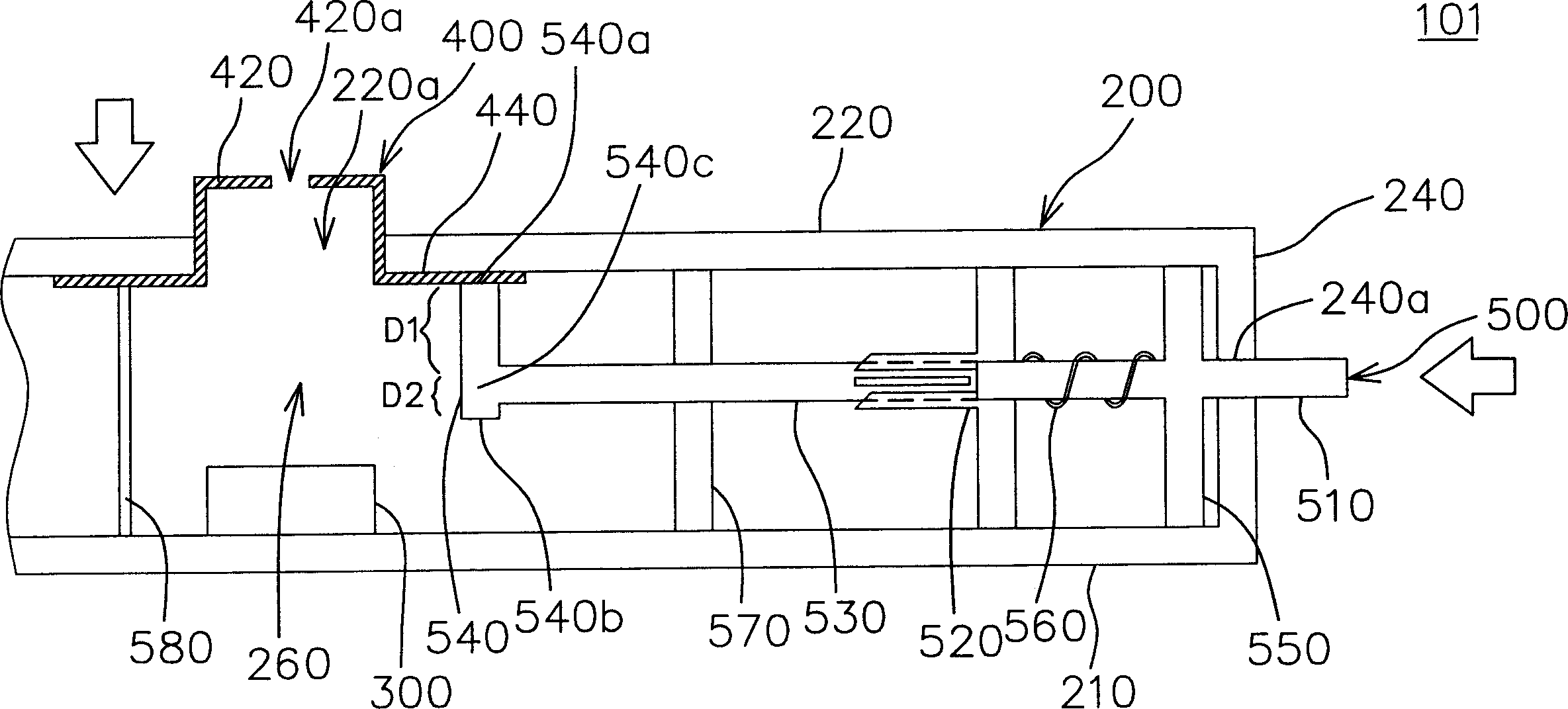
[0029] exist Figure 1~2 Among them, the electronic device 101 includes a casing 200 , a sound receiving component 300 , a floating casing 400 and a lifting adjustment mechanism 500 . The casing 200 has a first opening 220 a and a sound receiving space 260 , and the sound receiving component 300 is disposed in the sound receiving space 260 . The floating casing 400 is di...


PUM


Abstract

The invention relates to an electric device with floating receiving hole, which comprises a receiving element, a floating frame, and a lifting adjuster, wherein the frame has one opening and one receiving space; the receiving element is inside the receiving space; the floating frame has one receiving hole while it is inside the opening to form the receiving space between the floating frame and the frame; the lifting adjuster can move inside the frame and contact the floating frame to push the floating frame to move along the opening, to make the receiving hole float inside or outside the opening. The invention can adjust the size of receiving space, to improve the resonance effect and improve the receiving quality.

Description

technical field [0001] The invention relates to an electronic device, in particular to an electronic device with a floating sound hole. Background technique [0002] In today's era of rapid technological development, portable electronic devices have become an indispensable part of the daily life of modern people. Especially mobile phones, with their thin, light, small size and easy to carry features, can make it very convenient for modern people to communicate with others by phone anytime and anywhere. [0003] The radio mechanism of a traditional mobile phone includes a radio hole, a radio space and a microphone as a radio component, and the radio hole is arranged on the casing of the mobile phone. The radio space is set inside the casing and communicates with the outside world through the radio hole. The microphone is arranged in the sound receiving space for receiving sound through the sound receiving space and the sound receiving hole. [0004] During the process of c...

Claims


Application Information

Patent Timeline
Patent Type & Authority Applications(China)
IPC IPC(8): H04R1/28H05K5/00
Inventor 张木财黄裕峰
Owner ASUSTEK COMPUTER INC
Why Eureka
Try Eureka