Inking device of printing press

A technology for printing presses and equipment, applied in the field of inking equipment, which can solve problems such as frequent

Inactive Publication Date: 2007-01-10
KOMORI CORP
View PDF1 Cites 10 Cited by
  • Summary
  • Abstract
  • Description
  • Claims
  • Application Information

AI Technical Summary

Problems solved by technology

Therefore, once the printed product changes, the ink feed roller has to be replaced, requiring frequent adjustment of the ink feed roller

Method used


Image

  • Inking device of printing press
  • Inking device of printing press
  • Inking device of printing press

Examples


Embodiment 2

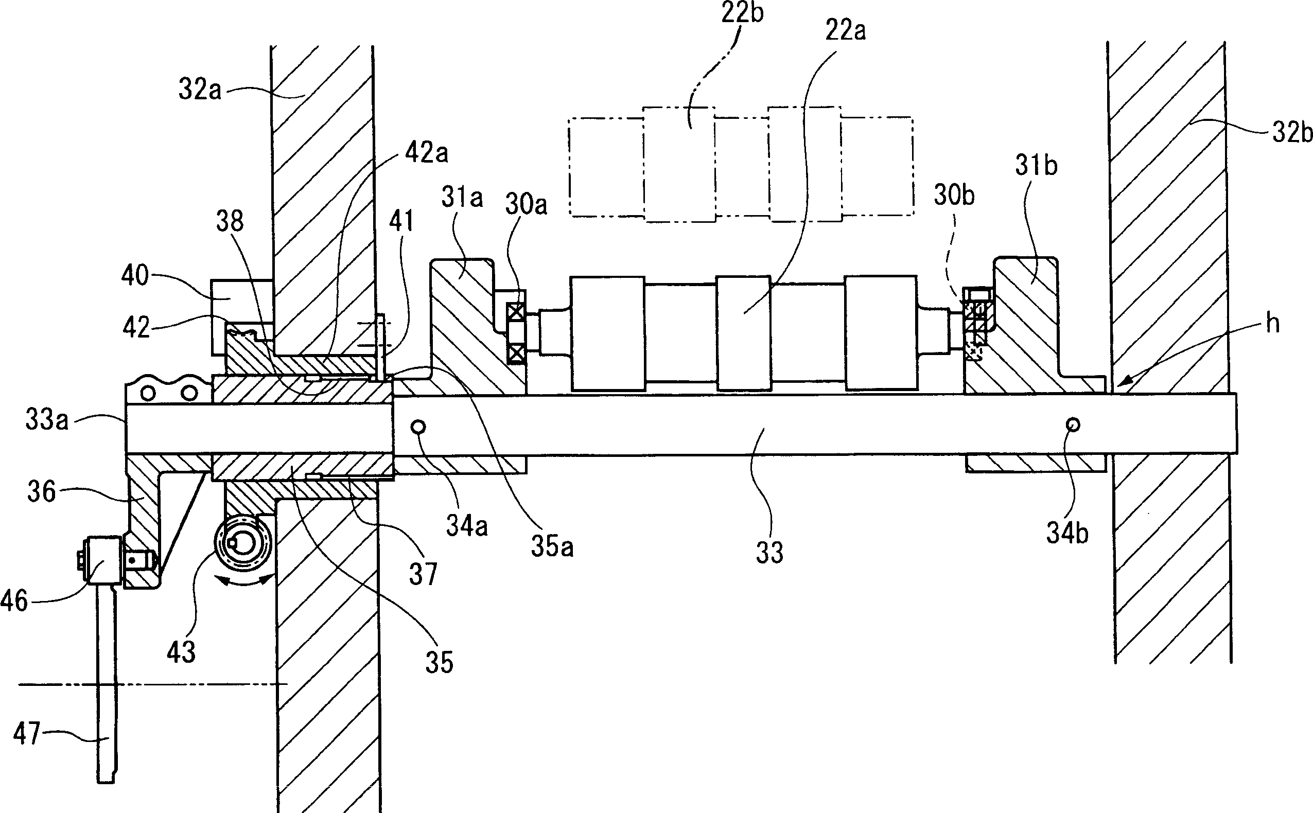
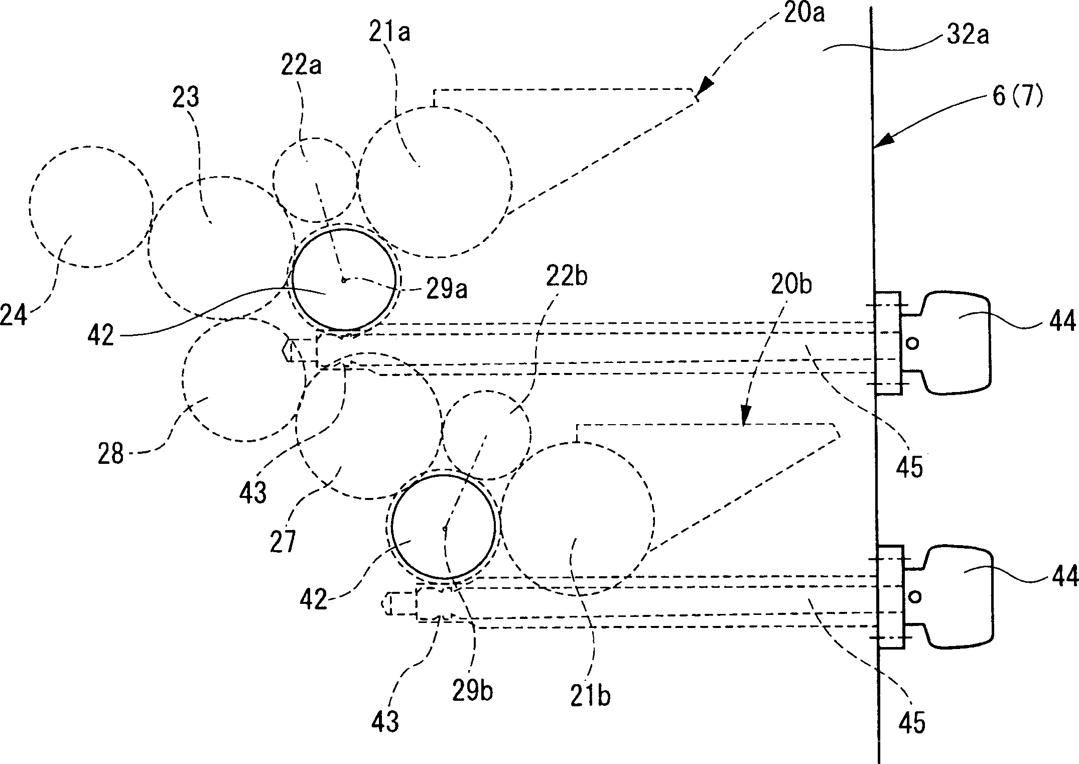
[0055] Figure 4 is a basic structural diagram of an inking unit, showing Embodiment 2 of the present invention. Figure 5 It is a structural diagram of the motor drive unit.

[0056] In this embodiment, the motor 53 is used to rotationally drive the worm shaft 43 in Embodiment 1 instead of the operating shaft 45 having the handle 44 with a dial, and the potentiometer 52 is used to detect the worm gear 42 integrated with the worm wheel 42 via the gears 50, 51. The amount of rotation of the bearing portion 42a (ie, the amount of movement of the ink feed rollers 22a, 22b). Other characteristics are identical with embodiment 1, therefore omit repeated description, and figure 1 The same parts in are given the same figure 1 The same reference numerals.

[0057] According to the above construction, in addition to the same actions and effects as in Embodiment 1, an advantage can be obtained that the position adjustment of the ink feed rollers 22a, 22b can be performed automatical...

Embodiment 3

[0059] Image 6 is a basic configuration diagram of an inking unit, showing Embodiment 3 of the present invention.

[0060] In this embodiment, the worm shaft 43 in Embodiments 1 and 2 is housed in the frame 32a to obtain a compact machine configuration. Other characteristics are identical with embodiment 1, therefore omit repeated description, and figure 1 with 4 The same parts in are given the same figure 1 with 4 The same reference numerals.

Embodiment 4

[0062] Figure 7 is a basic configuration diagram of an inking unit, showing Embodiment 4 of the present invention.

[0063] In this embodiment, the opposite ends of the shaft 33 in Embodiment 1 are formed as small diameter portions 33a, 33b; , 39b support to be rotatable and move (slide) along the axial direction of the needle bearings 60a, 60b; The diameter portion 33b is connected.

[0064] The operating shaft 45 as a driving device and having a dial handle 44 is rotatably supported parallel to the shaft 33 by the frame 32b via a support 64 assembled in an L-shape and also serving as a bracket 61 as a moving member. (to be described later). A pair (ie, left and right) of rollers 62a and 62b as engaging portions and restricting members is rotatably provided on a bracket 61 screwed onto the threaded engagement portion 45a of the operation shaft 45 and slidably fitted On the guide rod portion 64 a of the support member 64 . The aforementioned disk 63 is positioned between...


PUM


Abstract

An inking device of a printing press, including an ink ductor roller reciprocating between a receipt position, at which the ink ductor roller contacts an ink fountain roller to receive ink, and a transfer position, at which the ink ductor roller contacts an ink distribution roller or a first intermediate roller located downstream in an ink transfer direction to pass the ink on to the roller, comprises: a pair of split clamping holders supporting the ink ductor roller and supported swingably; and moving means, comprising a shaft, a sleeve, a bearing portion, a worm wheel, a worm shaft, and an operating shaft having a dial-equipped handle, for moving the pair of split clamping holders in the axial direction of the ink ductor roller.

Description

technical field [0001] The present invention relates to an inking device for a printing press, and more particularly to an inking device for a printing press preferably used for rainbow printing. Background technique [0002] A rainbow printing machine is disclosed in, for example, Japanese Patent Application Laid-Open No. 2001-310447. The printing press is a so-called double-pipe rainbow printing press, in which the ink flows only on the protrusions of each upper and lower inking roller with protrusions and recesses on the roller surface, and the ink flowing on these protrusions It is combined by the ink roller (ink distribution roller) to implement rainbow printing. [0003] Therefore, the lateral alignment between the upper and lower inking rollers is important, as is the lateral alignment of the protrusions of the upper and lower inking rollers with the plate cylinder (plate). [0004] When carrying out adjustment work for this purpose, it is common practice to loosen ...

Claims


Application Information

Patent Timeline
Patent Type & Authority Applications(China)
IPC IPC(8): B41F31/10B41F31/13B41F31/26
CPCB41F31/14
Inventor 日下明广
Owner KOMORI CORP
Why Eureka
Try Eureka