Warping system and warping method

A warping system and warping machine technology, applied in the warping system and the field of warping, can solve the problems of reduced production efficiency, disorder, temperature, humidity and other conditions changes, achieve small relative errors, reduce chaos or disorder, and reduce preparations effect of time

Inactive Publication Date: 2007-01-10
MURATA MASCH LTD +1
View PDF1 Cites 13 Cited by
  • Summary
  • Abstract
  • Description
  • Claims
  • Application Information

AI Technical Summary

Benefits of technology

The present technology allows for more efficient use of space during production compared with traditional methods like weaving machines. It achieves this through synchronized movement between different types of threads within one fabric instead of individually changing them separately. This reduces the complexity involved when making packages containing multiple thread colors. Additionally, it improves accuracy over existing systems due to its ability to determine which part needs to switch from another thread without actually having to stop working altogether. Overall, these technical improvements improve efficiency while reducing costs associated with producing packaging products.

Problems solved by technology

This technical problem addressed in this patented text relates to improving the process of producing high quality fibers with specific properties without requiring excessive amounts of materials. Existing methods involve individually wrapping each fiber bundle onto another beforehand, resulting in wasted material costs and decreased productivity compared to continuous winder techniques like roller warming.

Method used


Image

  • Warping system and warping method
  • Warping system and warping method
  • Warping system and warping method

Examples


Embodiment Construction

[0038] best practice

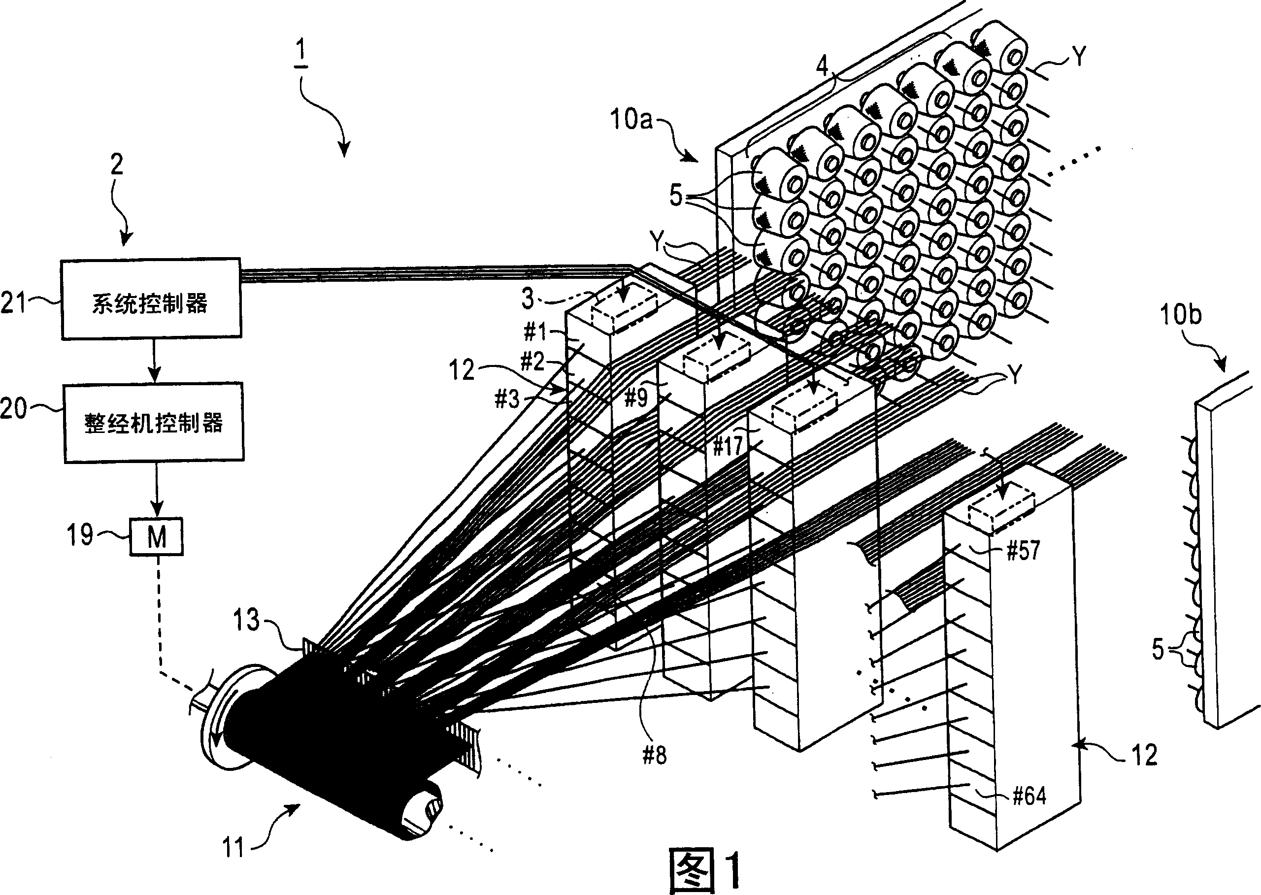
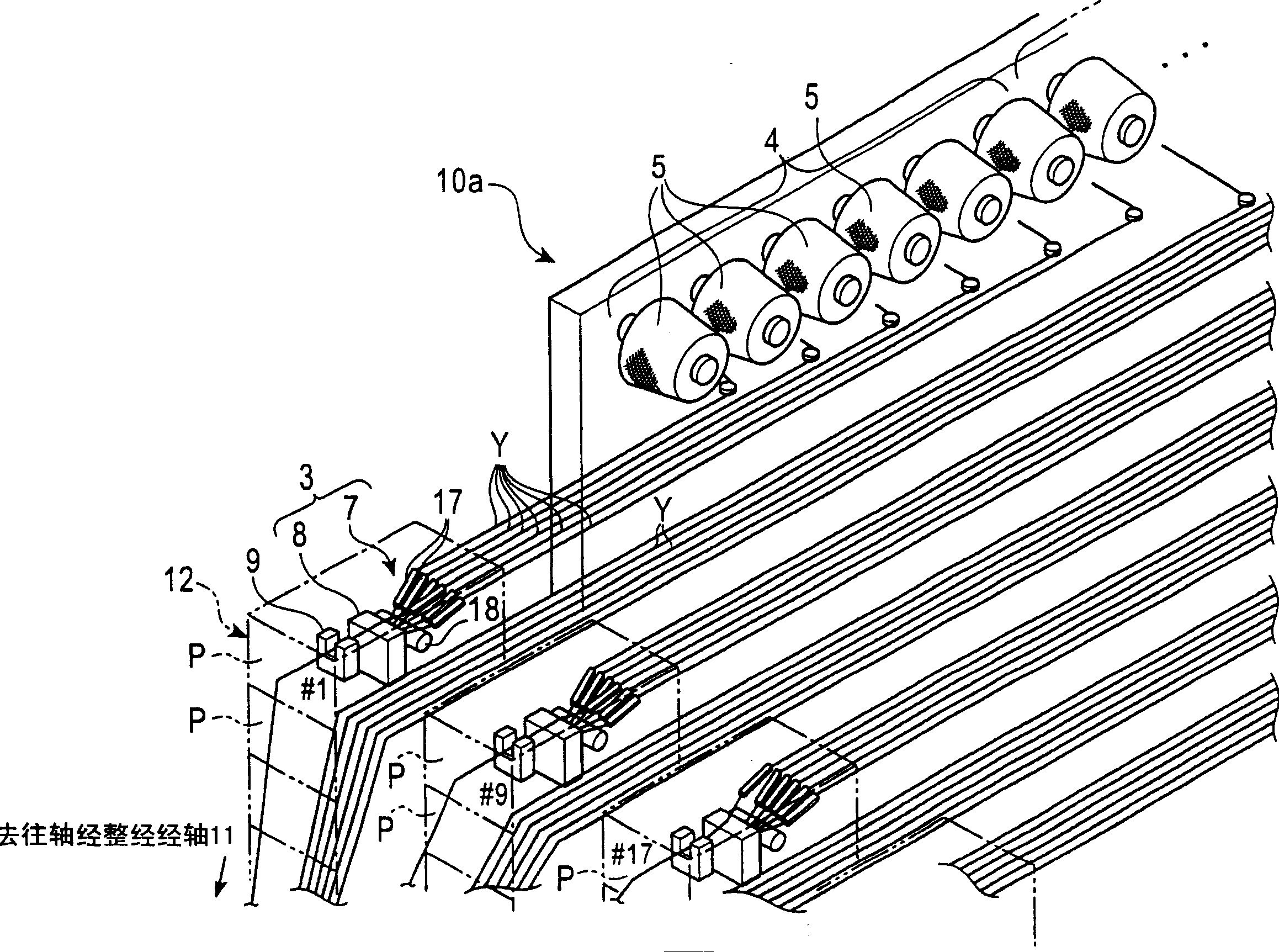
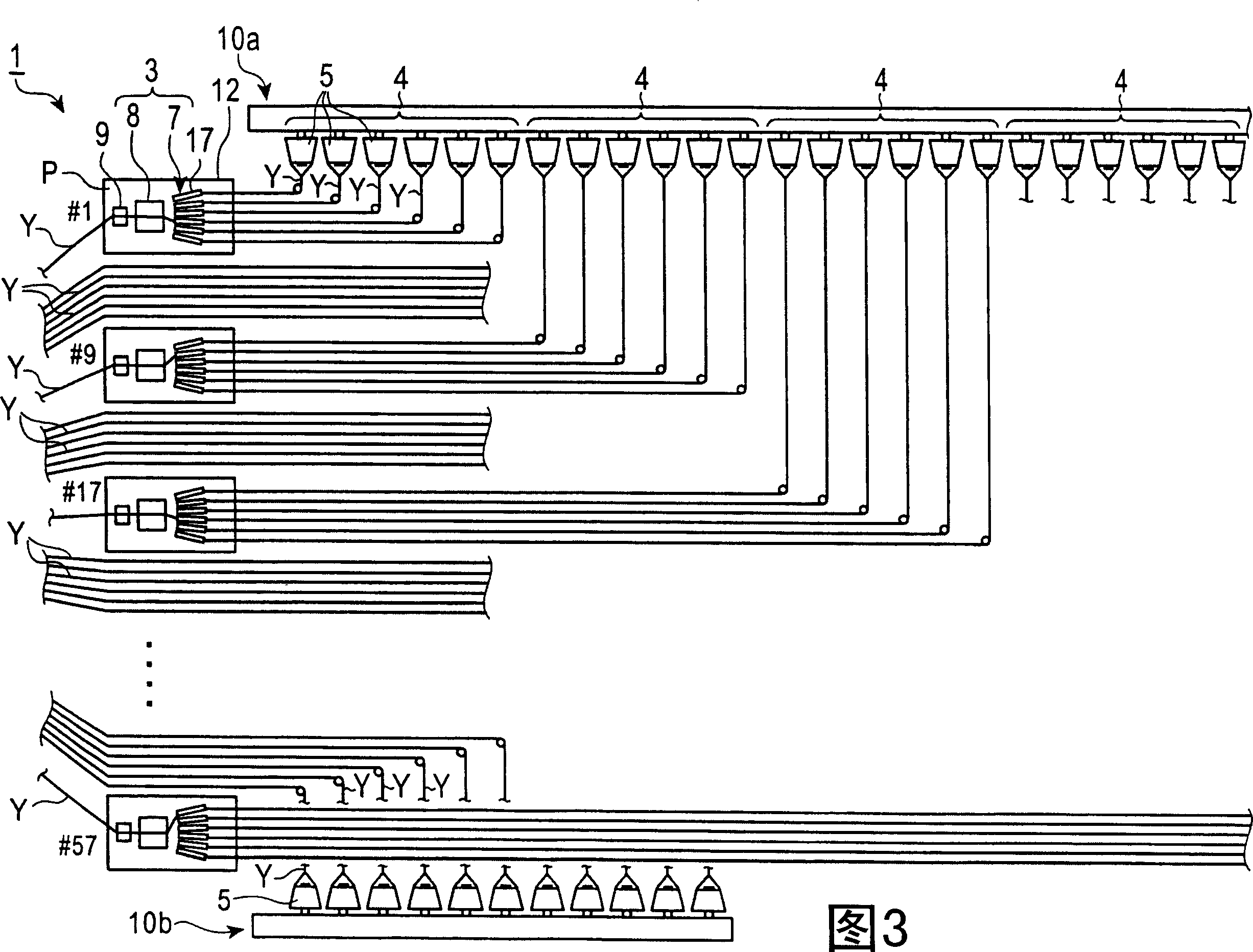
[0039] Embodiments of the invention will be described below. Fig. 1 is a perspective view showing the overall structure of a beam warping system related to an embodiment of the present invention, figure 2 Fig. 3 is an enlarged perspective view showing how a warp yarn group is supplied from a package group to a yarn switching mechanism, and Fig. 3 is a plan view showing an overall structure of a beam warping system according to an embodiment of the present invention, Figure 4 It is a longitudinal sectional view showing the appearance and arrangement of the yarn switching mechanism.

[0040]Fig. 1 shows a perspective view of the whole of the beam warping system. 2. The warping creel 10b and the beam warping machine 2 that winds hundreds of warp yarns Y unwound from the yarn feeding package 5 in parallel to form a beam warping beam 11.

[0041] In addition, the beam warping system 1 is provided with a plurality of warping beams for accommodating multipl...


PUM


Abstract

The present invention provides an arrangement that enables diverse patterns to be inexpensively made in a warping system 1 that winds a predetermined length of warps Y supplied from warping creels 10a, 10b to form a warping beam 11. A plurality of yarn switching mechanisms 3 are arranged in a yarn path formed between the warping creel 10a and the warping beam 11; each of the yarn switching mechanisms 3 includes a yarn selecting device 7 and a splicing device 8 that splices a selected warp. Package groups 4 each including a plurality of supplying packages 5 of different yarn colors or the like are set on the warping creel 10a in association with the respective yarn switching mechanisms 3. A warp group Y, Y, ... unwound from the package group 4 are supplied to the yarn selecting device 7 in the yarn switching mechanism 3. The yarn selecting device 7 selects and supplies at least one warp Y of the supplied warp group Y, Y, ... to the warping beam 11 side. All or selected ones of the yarn switching mechanisms 3, 3, ... are actuated to switch the warps Y within the winding length of the warping beam 11.

Description


Claims


Application Information

Patent Timeline
Owner MURATA MASCH LTD
Why Eureka
Try Eureka