Glass top plate for drop-in type cooking stove

A technology for glass panels and stoves, which is applied in the field of glass panels, and can solve problems such as large opening area, insufficient combustion air volume, and difficulty in adequately supplying combustion air.

Inactive Publication Date: 2007-01-10
RINNAI CORP
View PDF2 Cites 9 Cited by
  • Summary
  • Abstract
  • Description
  • Claims
  • Application Information

AI Technical Summary

Problems solved by technology

[0004] However, because the height of the hanging wall portion of the rear frame is limited by the design and cannot be made so high, the opening area of ​​the vent opening on the hanging wall portion cannot be ensured to be large e...

Method used


Image

  • Glass top plate for drop-in type cooking stove
  • Glass top plate for drop-in type cooking stove
  • Glass top plate for drop-in type cooking stove

Examples


Embodiment Construction

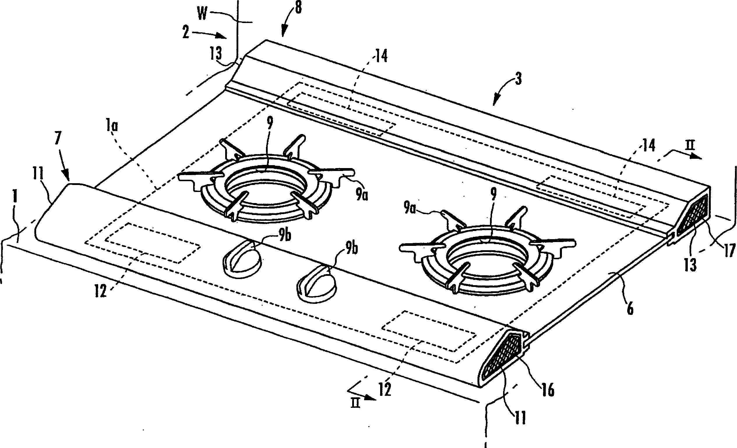
[0032] Below, refer to figure 1 An example of embodiment of the glass panel for built-in stoves of this invention is demonstrated to FIG. 8. FIG. First, explain figure 1 and figure 2 The glass panel of the 1st example of the 1st Embodiment shown.

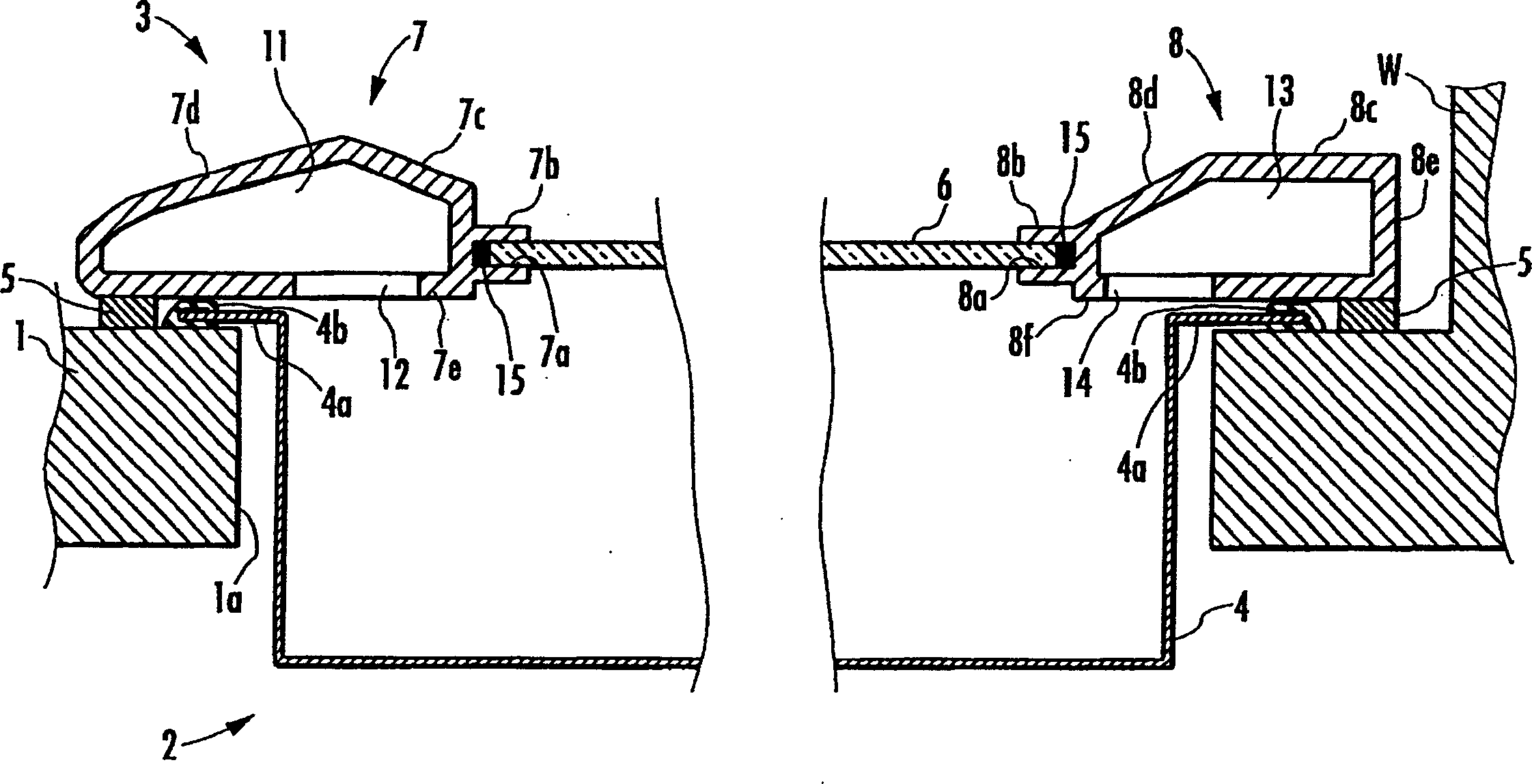
[0033] figure 1 Shown is the state of assembling the built-in stove 2 on the countertop 1 of the kitchen system. The stove 2 has: a glass panel 3 placed on the surface of the countertop 1, and figure 2 The shown upper surface is a box-shaped furnace body 4 with an open surface. On the upper edge of the furnace main body 4, a flange portion 4a protruding outward is formed. Therefore, when the stove main body 4 is dropped into the opening 1a provided on the table top 1, the flange portion 4a is locked on the opening edge of the stove opening 1a, and the stove main body 4 is suspended on the table top 1. .

[0034] In addition, a gasket 4b is provided on the outer peripheral edge of the flange portion 4a, and the flange po...


PUM


Abstract

The glass top plate is provided with a top plate main body 6 made of glass, and a front frame body 7 and a rear frame body 8 using a metal extrusion-molded material. The front frame body 7 has a first vent holes 11 on left and right sides, and a second vent hole 12 on a bottom face. The rear frame body 8 has third vent holes 13 on left and right sides, and a fourth vent hole 14 on a bottom face. The second vent hole 12 and the fourth vent hole 14 face a cooking stove opening 1a of a counter top 1, and they are communicated with the cooking stove body. When combustion of a burner 9 is carried out, combustion air in the cooking stove body is consumed, and air is supplied into the cooking stove body from the first vent holes 11 and the second vent hole 12 in the front frame body 7, and from the third vent holes 13 and the fourth vent hole 14 in the rear frame body 8. By this, even when the space between the wall face W and the rear frame body 8 is narrow, air can be sufficiently supplied into the cooking stove body.

Description

technical field [0001] The present invention relates to a glass panel for a built-in stove that is arranged such that a stove main body falls into an opening formed on a countertop. Background technique [0002] It is well known that, in the past, on such a built-in stove, as a panel, a glass panel with glass as the main part (panel body) has been used in consideration of the advantages of appearance and cleaning (for example, refer to JP-A 11 - Bulletin No. 22981, 0026~0028, Figure 1 ~ Figure 3 ). The glass panel is composed of a glass panel body and an outer frame surrounding the periphery of the panel body. In addition, the outer frame is formed by connecting the front frame parts along the front part of the panel body, the left and right side frame parts along the left and right side parts of the panel body, and the rear frame parts along the rear part of the panel body. shape, to form. [0003] In addition, in the built-in stove, the airtightness of the stove body i...

Claims


Application Information

Patent Timeline
IPC IPC(8): F24C15/12
CPCF24C3/00F24C15/08F24C15/101
Inventor 水谷嘉宏
Owner RINNAI CORP
Why Eureka
Try Eureka