

Metal coating panel with touch control induction isolation zone and its producing method
A technology of metal coating and isolation area, which is applied in the field of separately designed panels, which can solve problems such as the inability to use capacitive touch switches in combination
- Summary
- Abstract
- Description
- Claims
- Application Information
AI Technical Summary
Problems solved by technology
Method used
Image

Examples
Embodiment Construction
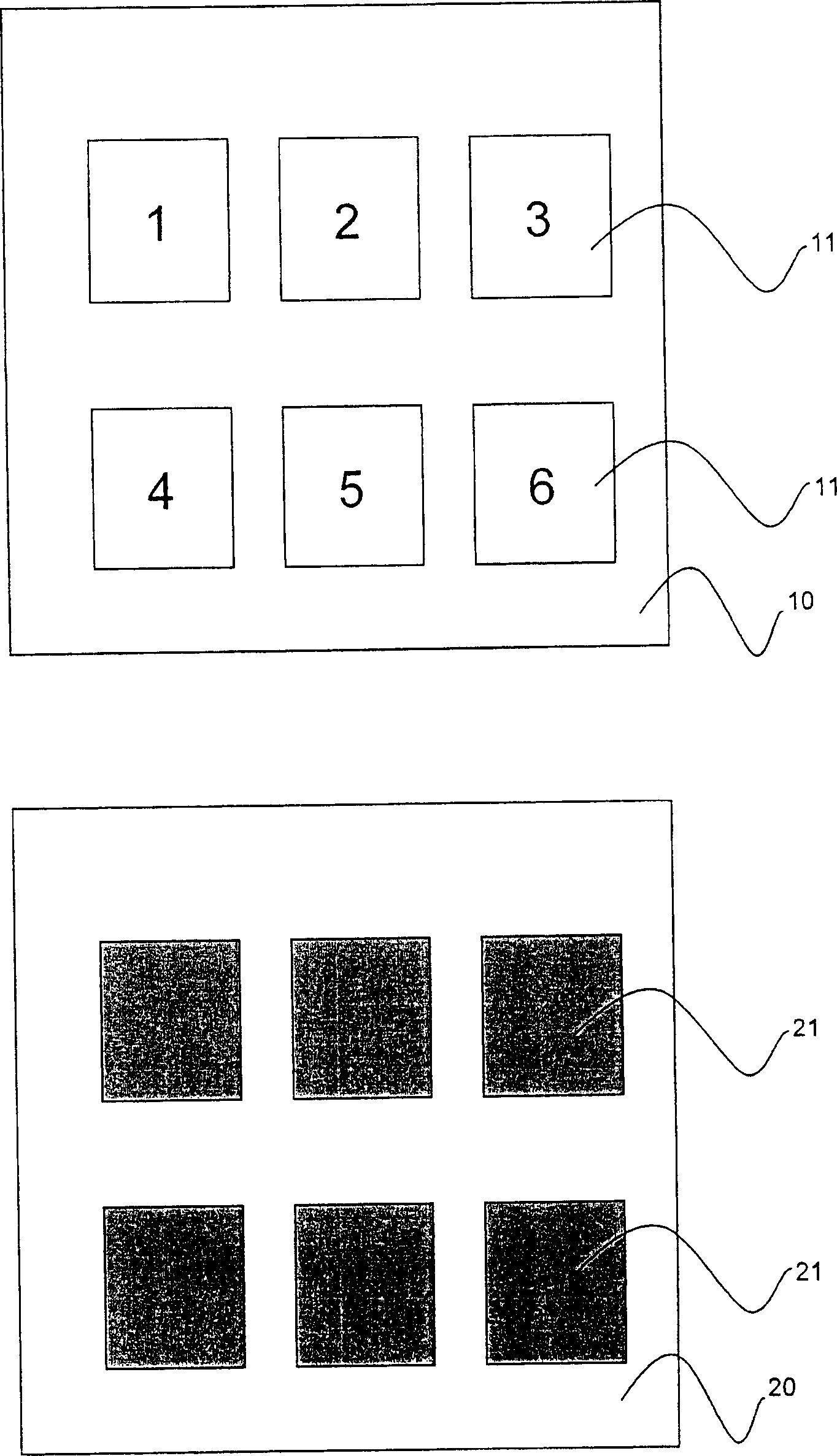
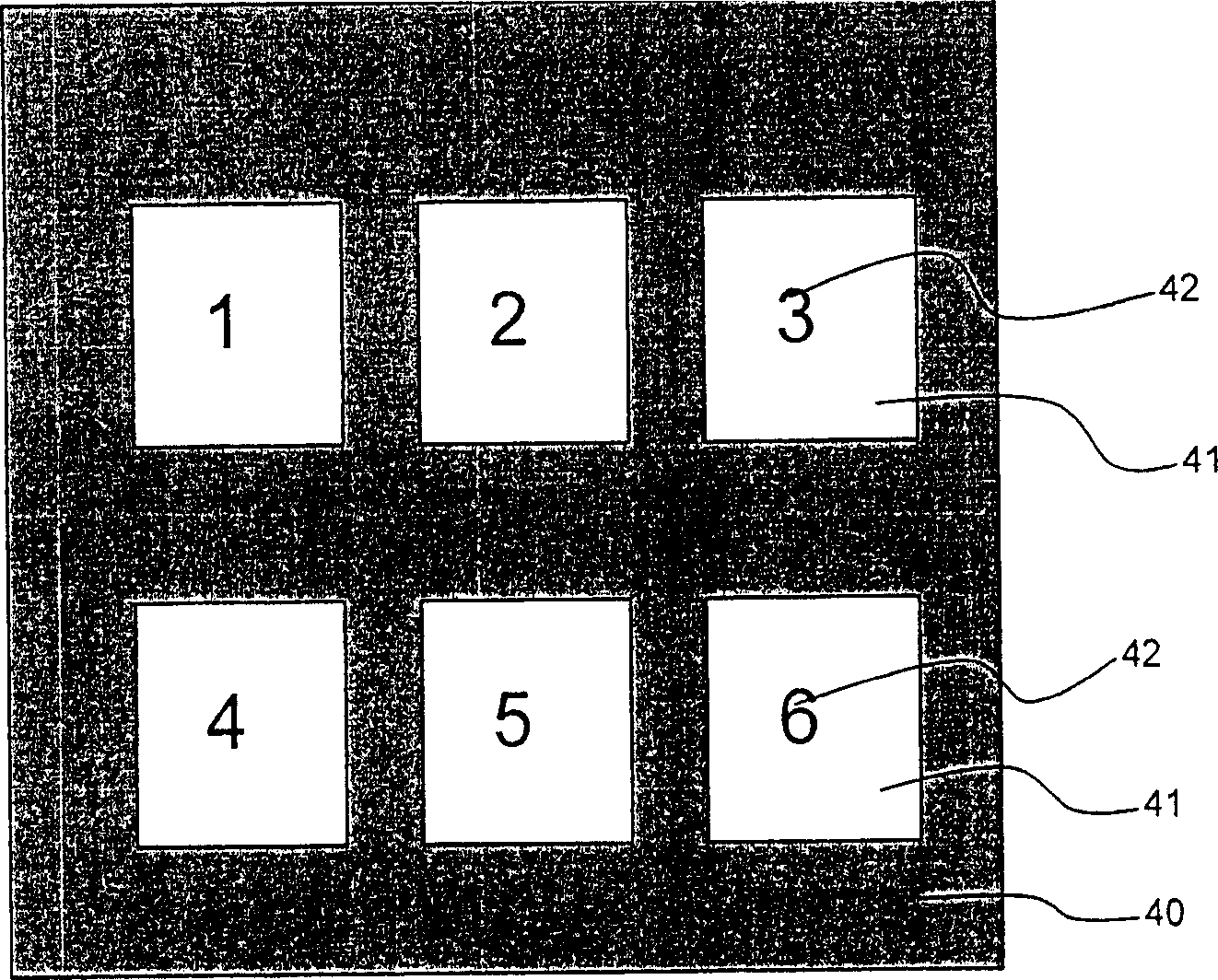
[0019] see figure 1 , 3 As shown, the first embodiment of the present invention with a metal-coated panel with a touch-sensitive isolation area and its manufacturing method is to make a metal-coated panel 40 corresponding to figure 1 The position of the capacitive touch switch 21 of the printed circuit board 20 shown forms at least one isolation unit without metal coating, such as a block 41, and a key mark 42 is marked on the block 41, so that each block 41 Isolated from each other and not distinguishable by electrical continuity with the entire metal coating. When the user's finger touches a certain block 41, the capacitive touch switch 21 corresponding to it will be sensed and activated, and other capacitive touch switches 21 not corresponding to it will be activated, and there will be no induction. Unfavorable and unsensing conditions.
[0020] see figure 1 , 4 As shown, the second embodiment of the metal-coated panel with a touch-sensitive isolation area and its manu...
PUM
 Abstract
Description
Claims
Application Information