Installing and closure method of steel arched bridge arch rib large segment and lifting system

A lifting system and technology for steel arch bridges, applied in bridges, bridge construction, erection/assembly of bridges, etc., can solve problems such as long construction period, low installation accuracy of arch ribs, and influence on navigation

Inactive Publication Date: 2007-01-31
CHINA RAILWAY ENG CONSULTING GRP CO LTD
View PDF0 Cites 18 Cited by
  • Summary
  • Abstract
  • Description
  • Claims
  • Application Information

AI Technical Summary

Problems solved by technology

[0007] The first purpose of the present invention is to provide a large-section installation method for steel arch bridge arch ribs in view of the technical defects of t

Method used


Image

  • Installing and closure method of steel arched bridge arch rib large segment and lifting system
  • Installing and closure method of steel arched bridge arch rib large segment and lifting system
  • Installing and closure method of steel arched bridge arch rib large segment and lifting system

Examples


Embodiment 1

[0057] figure 2 It is a flow chart of Embodiment 1 of the installation closing method of the present invention. like figure 2 As shown, this embodiment includes steps:

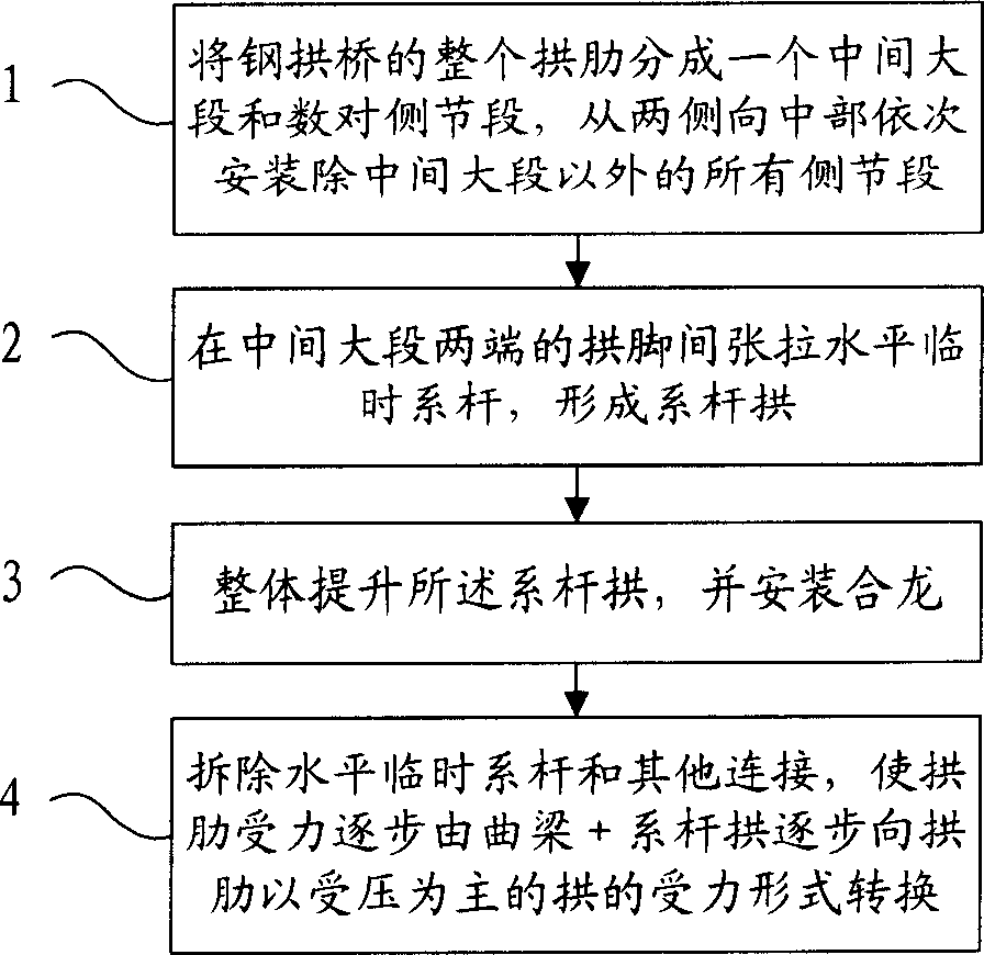
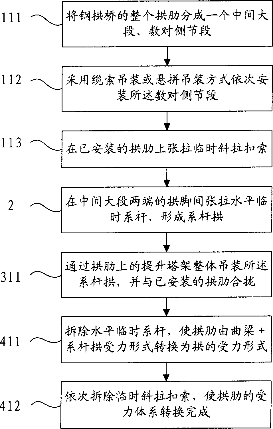
[0058] Step 111, dividing the entire arch rib of the steel arch bridge into a large middle section and several pairs of side sections;

[0059] Step 112. Install the pairs of side segments sequentially by means of cable hoisting or suspension hoisting;

[0060] Step 113, tensioning temporary cable-stayed buckles on the installed arch ribs;

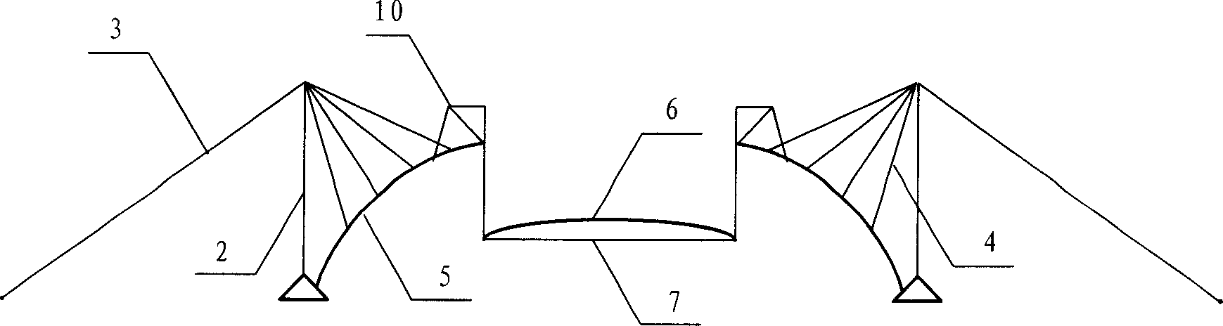
[0061] Step 2. Stretch horizontal temporary tie rods between the arch feet at both ends of the middle section to form a tie rod arch;

[0062] Step 311, integrally hoisting the tie-rod arch through the hoisting tower on the arch rib, and closing it with the installed arch rib;

[0063] Step 411, remove the horizontal temporary tie rods, so that the stress of the arch ribs is gradually converted from the stress of the curved beam + the tie rod arch to the stress form...

Embodiment 2

[0067] Figure 4 It is a flow chart of Embodiment 2 of the installation closing method of the present invention. like Figure 4 As shown, this embodiment includes steps:

[0068] Step 121, dividing the entire arch rib of the steel arch bridge into a middle section and a pair of side sections;

[0069] Step 122, lifting the large side section into place and supporting it on the outer lifting tower and the middle lifting tower;

[0070] Step 2. Stretch horizontal temporary tie rods between the arch feet at both ends of the middle section to form a tie rod arch;

[0071] Step 321, lifting the tie bar arch through a hoisting system consisting of a back cable, a middle hoisting tower, and a pressing tower cable, and closing it with the pair of side large sections;

[0072] Step 421, removing the horizontal temporary tie rods, so that the stress of the arch ribs is gradually converted from the stress form of the curved beam + tie arch to the stress form of the arch rib mainly un...


PUM


Abstract

This invention relates to a kind of steel arch bridge arch rib's big segment installing closure method and hoisting system. The installing closure method includes the following steps: divide the whole arch rib into one middle big segment and several pairs side segments, then install all the side segments except the middle big segment from side to middle, pull the level temporary tie bar to form the tie bar arch among the middle big segment both sides' arch springing, upgrade the tie bar arch and install closure, remove the level temporary tie bar and other temporary support, convert the arch rib's power form which is from bent girder and tie bar arch to the arch. The hoisting system includes two middle lift towers and pressing tower cable. The two middle lift towers connect with two-back-cable's and two-sling's one end. The other end of two-sling connects with the waiting upgrade's middle big segment. The other end of two-back-cable connects with anchor block. The back-cable is synchronization pulling back-cable which bases on the sling's level function power to middle lift tower, it uses the synchronization adjust pulling power. This invention simplifies the construction step and improves the closure's precision. It lowers the construction difficulty and shortens the construction period.

Description

technical field [0001] The invention relates to a method for installing and closing a large-span arch bridge and a lifting system, in particular to a method for installing and closing a large segment of an arch rib of a steel arch bridge using the technology of large-span lifting and beam closing technology, and a large arch rib of a steel arch bridge implementing the method. The segment is installed with the Helong lifting system. Background technique [0002] With the development of transportation construction, the technology of long-span bridges has been greatly improved. Because of the arch bridge's curved shape and aesthetic feeling that other bridge types cannot match, it is easier for designers to have more room for bridge aesthetics. Therefore, many long-span arch bridges have been built in China in recent years. The construction of long-span arch bridges shows that the main stress-bearing structure of arch bridges—the arch ribs are mostly space curves, which brings...

Claims


Application Information

Patent Timeline
IPC IPC(8): E01D21/00E01D21/10
Inventor 徐升桥任为东彭岚平李辉张华辛兵卢大兴
Owner CHINA RAILWAY ENG CONSULTING GRP CO LTD
Why Eureka
Try Eureka