
Tray valve for a tray column

A technology of plate towers and trays, applied in the direction of control valves, valve devices, functional valve types, etc., can solve problems such as easy deformation

Inactive Publication Date: 2007-02-07
SULZER CHEMTECH AG
View PDF2 Cites 6 Cited by
  • Summary
  • Abstract
  • Description
  • Claims
  • Application Information

AI Technical Summary

Problems solved by technology

The disadvantage of this valve structure is that the guide protruding part is easily deformed

Method used


Image

  • Tray valve for a tray column
  • Tray valve for a tray column
  • Tray valve for a tray column

Examples


Embodiment Construction

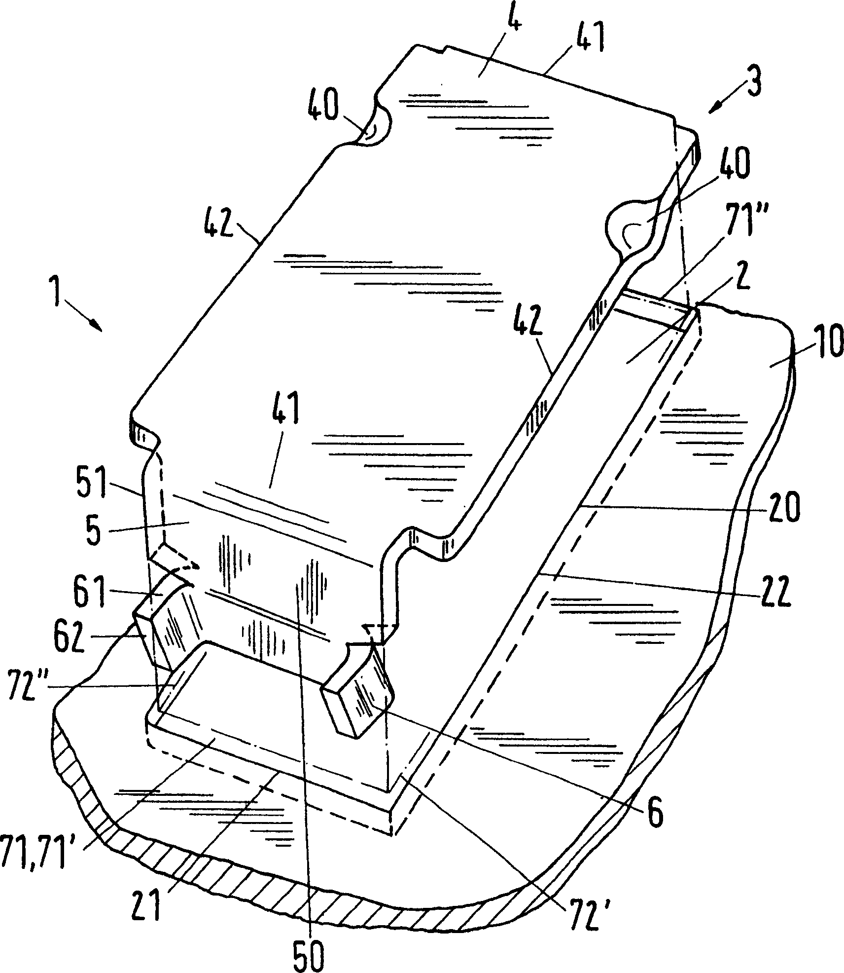
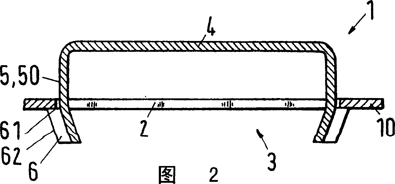
[0018] A first embodiment of a tray valve 1 having a tray opening 2 in a tray 10 and a valve body 3 according to the invention is shown in figure 1 and 2 in. The valve body 3 allowing variable passage of steam through the tray opening 2 is shown separately therefrom. FIG. 2 shows a longitudinal section through a tray valve 2 with an insert valve body 3 . The valve body 3 , made to cooperate with the edge 20 of the opening, comprises a top plate 4 and two guide projections 5 arranged at the edge of the plate 3 and directed vertically downwards. The edge 20 of the opening has a rectangular shape with two short sides 21 and two long sides 22 . The top plate 4 accordingly has four straight sides 41 and 42 lying on a rectangle, wherein the side 41 is curved and the side 42 rests outside the edge 20 of the opening above the tray 10 . The guide extension 5 has barbs 6 by which the valve body 3 is anchored on the opening edge 20 so that the stroke is limited and the valve body 3 ca...


PUM


Abstract

In a plate valve (1) for a plate column including a vapor passage opening (2) in the plate (10) and a valve body (3) with a lid plate (4) and a guiding side-piece (5), provided with barbs (6) for anchoring the valve body in the opening, the valve body is of material and shape allowing elastic deformation on insertion into the opening, the deformation being mainly restricted to arching of the lid plate. A plate valve (1) for a plate column includes a vapor outlet opening (2) in the plate (10), an opening edge (20) and a valve body (3) adapted to the opening. The valve body consists of a lid plate (4) and a guiding side-piece (5), directed vertically downwards at the edge of the plate and provided with barbs (6) for anchoring the valve body on the opening edge. The outer surfaces of the guiding piece contain a lifting region lifting region (50) perpendicular to the plane of the plate edge, which optionally has downwardly directed dimples. The novel feature is that the valve body is of material and shape allowing elastic (and optionally partially plastic) deformation on insertion into the opening, the deformation being mainly restricted to arching of the lid plate and possible deformation being reversible up to a slight residual deformation. The lid plate optionally has weakened sites (e.g. grooves, slits or holes) to facilitate arching on insertion in the opening. Independent claims are also included for the following: (1) a plate column in which each plate (10) has multiple plate valves as above; and (2) inserting the plate valve bodies into the column, by applying force to the lid plate (e.g. with a blow) so that the plate arches, barbs in the interior surface of the opening swivel and the guiding side-piece and its barbs enter the opening in a snap fitting.

Description

technical field [0001] The invention relates to a tray valve for a tray column according to the preamble of claim 1 . The gas phase (steam) contacts the liquid phase on the trays of the tray column. Tray valves for this type of tray column use a movable valve body to allow the passage of steam variably through the tray openings. The invention relates to a method for inserting a valve body into a tray opening. Background technique [0002] A tray valve for circular tray openings is known from GB-A-1018924. The valve body of such a tray valve includes a plurality of guide limbs attached to the edge of the circular top plate and perpendicular to the plate. Barbs for anchoring the valve body are arranged at the guide extension. The valve body can be manually inserted into the tray opening, wherein the guide projection and / or the barb are elastically deformed. Depending on the material, plastic deformation can occur which can be reversed by additional manipulation after inse...

Claims


Application Information

Patent Timeline
IPC IPC(8): B01D3/20
CPCB01D3/163F16K15/023
Inventor M·费希尔I·多布罗夫斯基V·库尔蒂E·费尔
Owner SULZER CHEMTECH AG
Learn More