

Reduced-pressure drying apparatus
一种减压干燥装置、减压腔的技术,应用在干燥固体物料、不加热来干燥固体材料、烘干等方向,能够解决膜厚均匀性下降、蒸气浓度差异、分布不同等问题
Inactive Publication Date: 2007-02-07
SEIKO EPSON CORP
View PDF1 Cites 25 Cited by
- Summary
- Abstract
- Description
- Claims
- Application Information
AI Technical Summary
Problems solved by technology
Therefore, using the above-mentioned prior art decompression drying device, even after setting the rectifying plate, the air flow of the solvent evaporated from the liquid under reduced pressure is controlled with a certain speed in a certain direction, and there is a problem in drying. The flow of liquid (convection) occurs during the process, and under the action of surface tension, the uniformity of film thickness decreases.
In addition, there is a problem that the distribution of vapor concentration (or pressure) differs between the central part and the peripheral part of the workpiece, and as a result, the in-plane distribution of the film thickness is different due to the difference in drying speed.
Furthermore, after adopting the structural design of the optimal drying device corresponding to the shape of various liquid materials and coated workpieces, there is also the problem of decreased versatility.
Method used
View moreImage
Smart ImageViewing Examples

Examples
Embodiment Construction
[0031]
Embodiments of the present invention will be described taking, as an example, a reduced-pressure drying device used in the step of forming an alignment film covering pixel electrodes of a pair of substrates constituting a liquid crystal panel of a liquid crystal display device.
Login to View More PUM
 Abstract
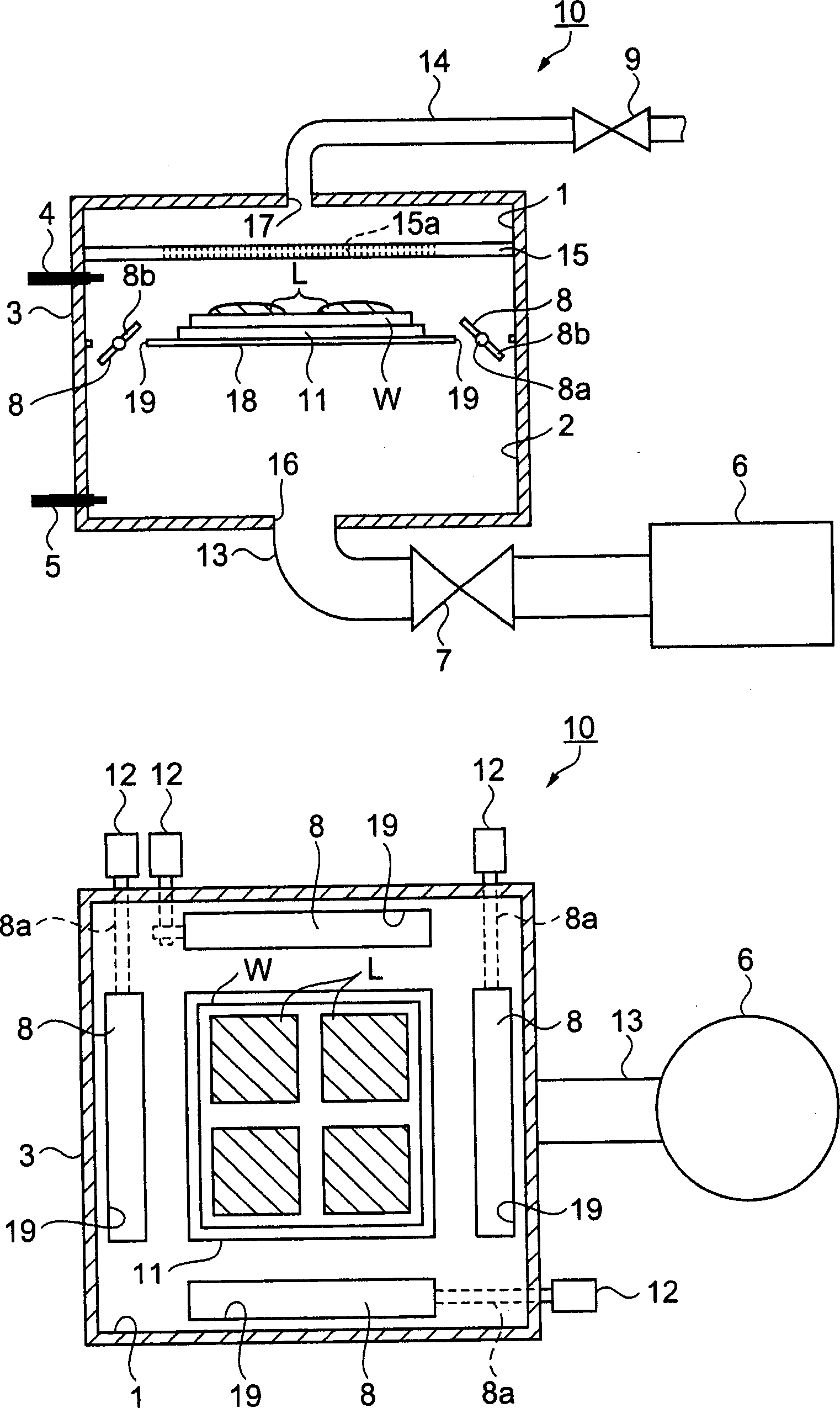
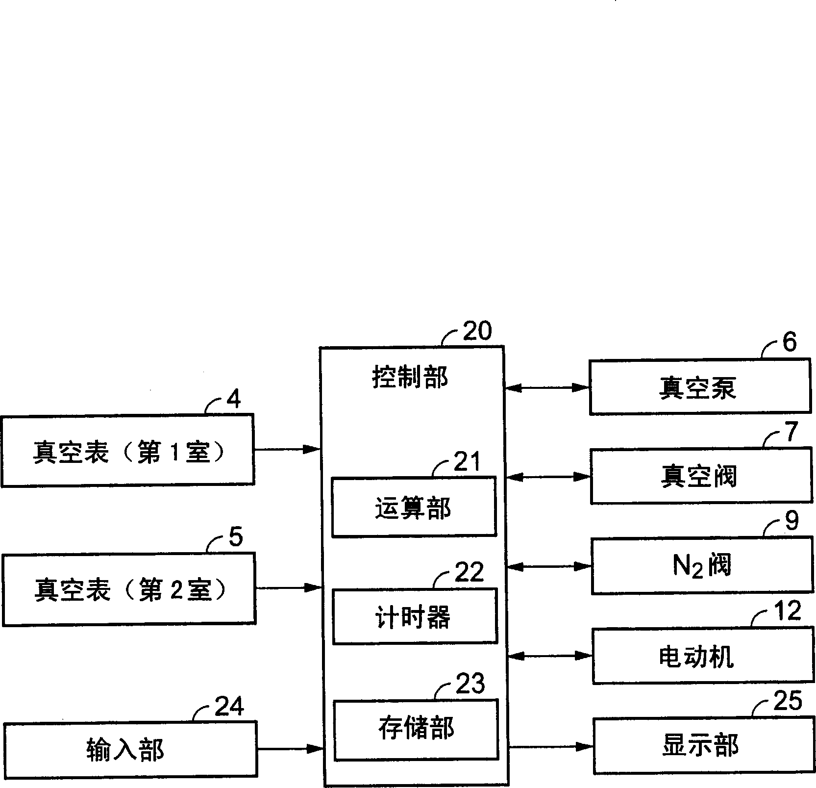
A decompression drier (10) is provided with a chamber (3) housing a substrate W applied with the liquid (L) and placed on a mounting block (11), and having a first chamber (1) and a second chamber (2), and a vacuum pump (6) used as a decompressing means provided in a state capable of decompressing the second chamber (2). It is provided with a communication port (19) used as a communication part provided in a bulkhead part (18) separating the first chamber (1) and the second chamber (2), and a communication valve (8) capable of opening and closing the communication port (19); a control part provided for controlling driving of the vacuum pump (6), and opening and closing of the communication valve (8), and vacuum gauges (4, 5) provided for detecting respective pressures of the first chamber (1) and the second chamber 2. The volume of the second chamber 2 is set such that it is larger than the volume of the first chamber 1. The decompression drier capable of optimizing an evaporation rate of an applied liquid solvent in response to the type of the liquid in a drying process, and capable of carrying out drying under reduced pressure with distribution of vapor pressure of the solvent held in a substantially even state.
Description
technical field [0001] The present invention relates to a reduced-pressure drying device used when a workpiece coated with a liquid is dried under reduced pressure to form a film on the surface of the workpiece. Background technique [0002] When coating a liquid containing a film-forming material on the surface of a wafer-like substrate such as a semiconductor to form a film, a vacuum drying device is used that evaporates a solvent component contained in the liquid under reduced pressure and then dries it. As this decompression drying device, there is a proposal that a rectifying plate is arranged to face the substrate in a chamber where the substrate coated with photoresist is placed and the pressure is reduced, and a vent hole is provided on the outer edge of the rectifying plate. (Patent Document 1). [0003] In the above-mentioned decompression drying device, exhaust is exhausted from the upper part of the decompression chamber, thereby forming an air flow in a c...
Claims
Login to View More Application Information
Patent Timeline
 Patent Type & AuthorityApplications(China)
IPC IPC(8): F26B5/04F26B25/00
CPCF26B5/04
Inventor五味一博
OwnerSEIKO EPSON CORP