

Writing tool provided with a valve feeding device
一种书写工具、阀门的技术,应用在书写器具、可连续调整的笔尖、印刷等方向,能够解决留下印记、书写工具正常操作有害、污迹等问题,达到有利于可靠性的效果
- Summary
- Abstract
- Description
- Claims
- Application Information
AI Technical Summary
Problems solved by technology
Method used
Image

Examples
Embodiment Construction
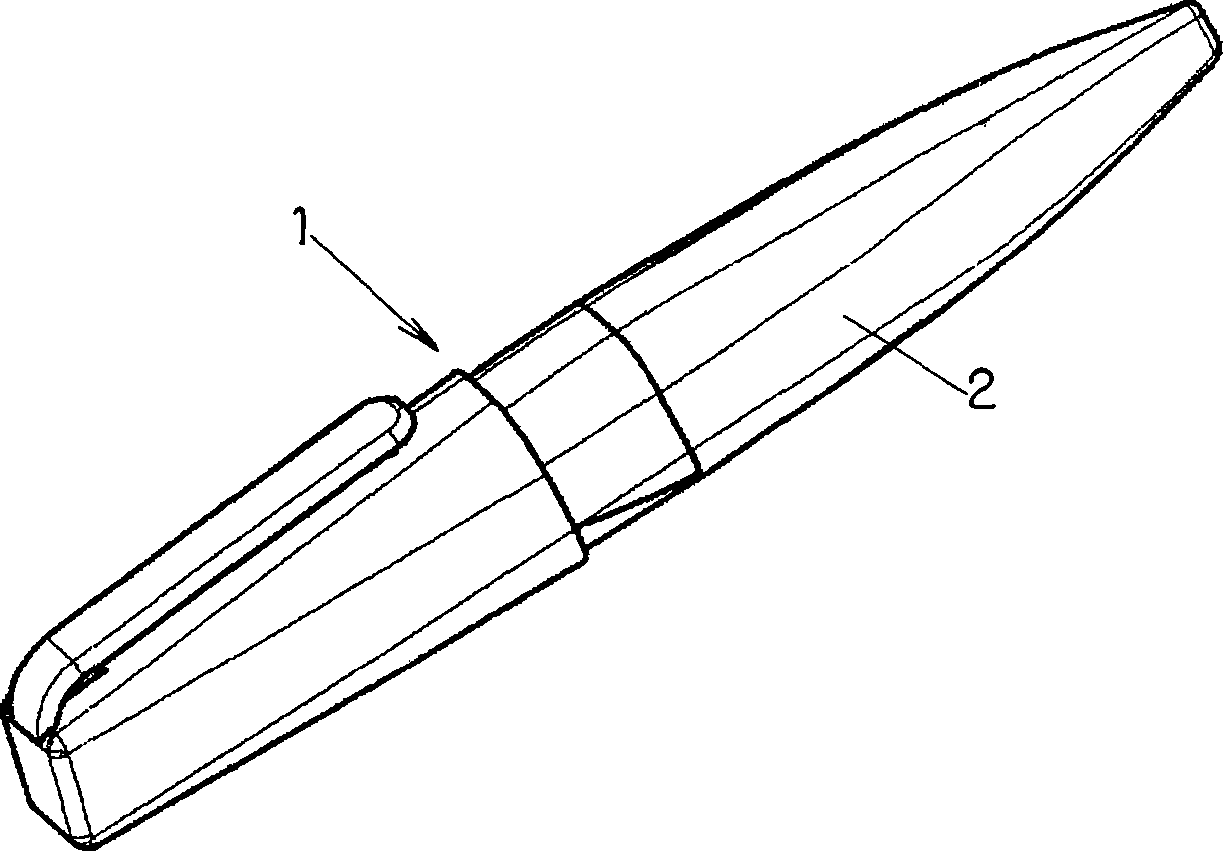
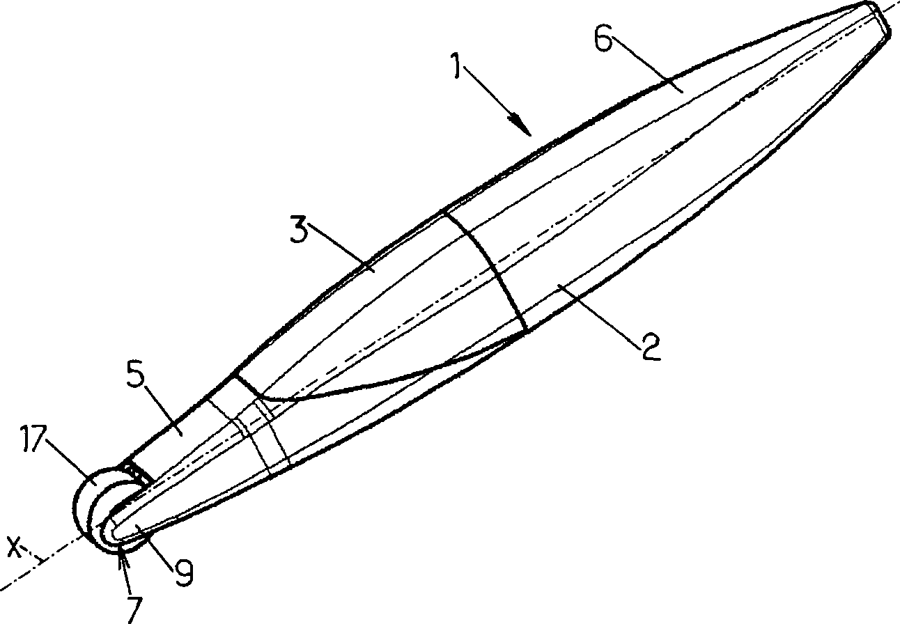
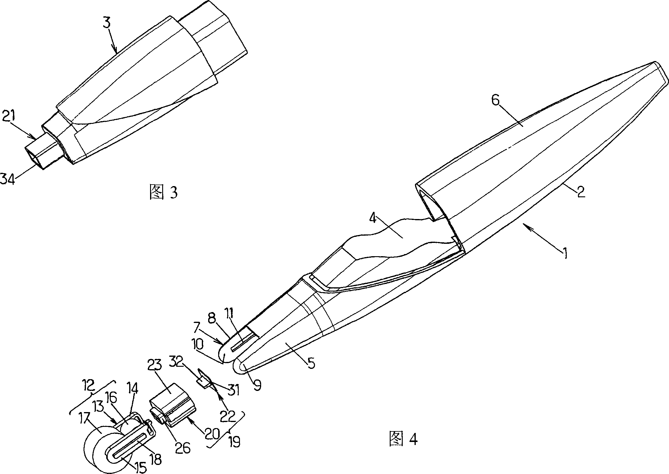
[0038] figure 1 The writing implement 1 in 4 has a tubular body 2 that is elongated along the main axis X, and this tubular body has an inner cavity 3 for liquid ink 4, especially referring to Fig. 4 , a part of the inner cavity is cut off in this figure 3.
[0039] As shown in Figures 3 to 5, the inner cavity 3 is a removable and replaceable modular barrel, which is just inserted between the front part 5 and the rear part 6 of the tube body 2. When the tube body 2 is assembled, the inner cavity 3 The surface is flush with the front 5 and the rear 6 ( figure 2 ).
[0040] As shown in particular in FIG. 4 , the front part 5 has at its end remote from the rear part 6 a fork-shaped front end 7 comprising two parallel arms 8 and 9 each having on its inner surface 10 an axis extending parallel to the main axis X. slot 11.
[0041] The tool 1 is preferably a marker pen or a line drawing pen, and also includes a writing device 12, which includes a support 13 with two bifurcation...
PUM
 Abstract
Description
Claims
Application Information