
Method for determining load of multiple-arch tunnel

A technology for multi-arch tunnels and determination methods, which is used in tunnels, earth-moving drilling, mining equipment, etc.

Inactive Publication Date: 2007-02-14
TONGJI UNIV
View PDF0 Cites 30 Cited by
  • Summary
  • Abstract
  • Description
  • Claims
  • Application Information

AI Technical Summary

Problems solved by technology

At present, the load determination of multi-arch tunnels generally takes the half-structure, and adopts the load determination method of single-cavity tunnels in the code, which is quite different from the actual stress situation

Method used


Image

  • Method for determining load of multiple-arch tunnel
  • Method for determining load of multiple-arch tunnel
  • Method for determining load of multiple-arch tunnel

Examples


Embodiment

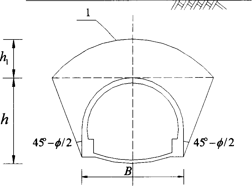
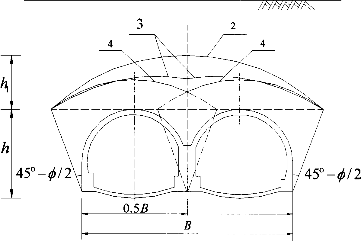
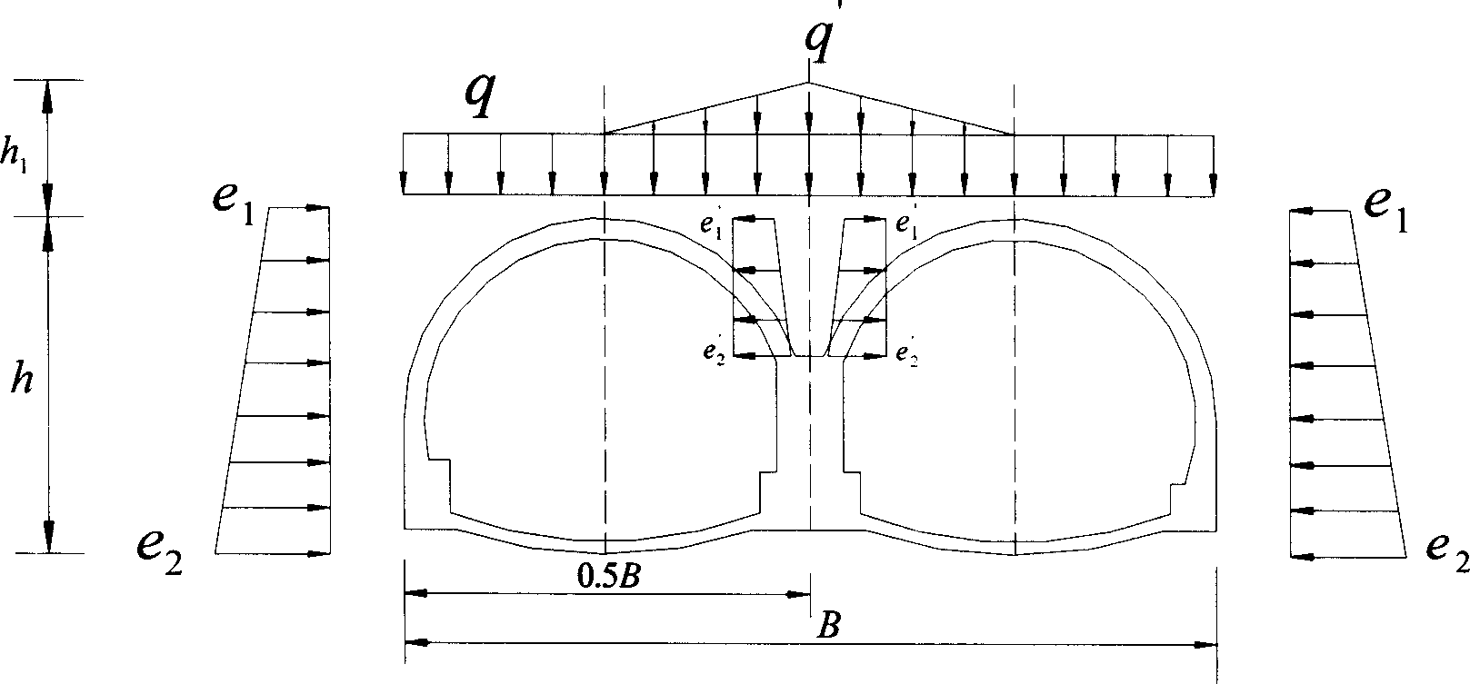
[0120] For a multi-arch tunnel with a buried depth of 29.7m, the calculated h q q , and its load is determined as follows:

[0121] vertical pressure

[0122] Additional load on the top of the middle wall q′=γ(H 1 -H)=75kN / m 2 ,

[0123] The horizontal surrounding rock pressure on both sides of the tunnel acting on the lining is:

[0124]

[0125] The horizontal surrounding rock pressure on both sides of the middle wall acting on the lining is:

[0126]

[0127] Example computational models such as Figure 6 shown.

[0128] Example bending moment as Figure 7 , Figure 8 shown.

[0129] Examples of axial forces such as Figure 9 , Figure 10 shown.

[0130] Example shear force such as Figure 11 , Figure 12 shown.

[0131] From Figure 9 , Figure 10 It can be seen that the axial force (2892kN) borne by the intermediate wall is basically the sum of the axial forces (2692kN) of the two linings of the left and right holes, and the thinnest point is equa...


PUM


Abstract

A method for confirming load of multi-arch tunnel includes confirming load mode of deep buried multi-arch tunnel based on suppose of double caving arch, confirming deep-shallow buried boundary of multi-arch tunnel according to deep-shallow burying boundary dividing manner in JTGD70-2004 specification for single hole tunnel and confirming load mode of shallow buried multi-arch tunnel by considering dead weight of triangle block at wall top in multi-arch tunnel.

Description

technical field [0001] The invention relates to a method for determining the load of a multi-arch tunnel. Background technique [0002] With the gradual expansion of the scale of my country's transportation infrastructure construction, the number of highway tunnels is also increasing, and new tunnel structure types and corresponding construction methods are also emerging, and the multi-arch tunnel is one of them. Compared with the traditional split-frame single tunnel, the multi-arch tunnel has a greater degree of freedom in the selection of line planes and opening positions, which is superior to split-frame tunnels; and because of its small footprint, this is to a certain extent This more than offsets the increase in construction costs while minimizing the impact on the environment. [0003] When the structural load method is used to calculate the tunnel, the load used generally uses the loosening pressure of the surrounding rock. The methods for determining the loosening ...

Claims


Application Information

Patent Timeline
IPC IPC(8): E21D9/00
Inventor 丁文其朱合华高世军李志厚李玉文蔡永昌王晓形李志刚
Owner TONGJI UNIV
Learn More