Braking device

A technology of braking device, transmission connection, applied in the direction of braking transmission device, brake, cooling brake, etc., can solve the problems of high cost and structure, no cooling cycle available, difficulty, etc.

Inactive Publication Date: 2007-02-14
VOITH TURBO GMBH & CO KG
View PDF4 Cites 14 Cited by
  • Summary
  • Abstract
  • Description
  • Claims
  • Application Information

AI Technical Summary

Benefits of technology

This patented technology solves problems with traditional methods for controlling vehicle's speed or stopping it from moving too much downhill on uneven surfaces such as snowy roads. It uses magnetic force instead of electricity to create resistance that slow down the car without causing damage when stopped at different speeds.

Problems solved by technology

This patents describes how we now have developed various technical solutions related to improving the performance and durability of temporary magnetic systems like those found at smaller cars. These improvements include adding more effective lubricants to improve their ability to absorb friction while reducing temperature buildup caused by excessive temperatures experienced during brazing operations. Additionally, some companies offer specialized equipment to help them manage these issues effectively without requiring expensive maintenance costs associated with permanently installed components.

Method used


Image

  • Braking device
  • Braking device
  • Braking device

Examples


Embodiment Construction

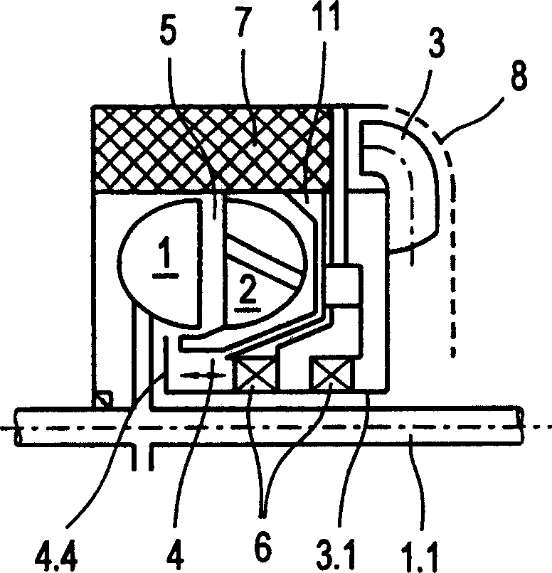
[0021] exist figure 1 The rotor 1 of the hydrodynamic retarder with the rotor shaft 1.1 by which it is rotatably arranged can be seen in FIG. The impellers of the rotor 1 together with the impellers of the stator 2 surrounding the rotor 1 delimit a torus-shaped working space 5 , in which a circulating flow is formed by the working fluid in the braking state. In general, this construction is known in reducers to a person skilled in the art, so no further explanation is required.

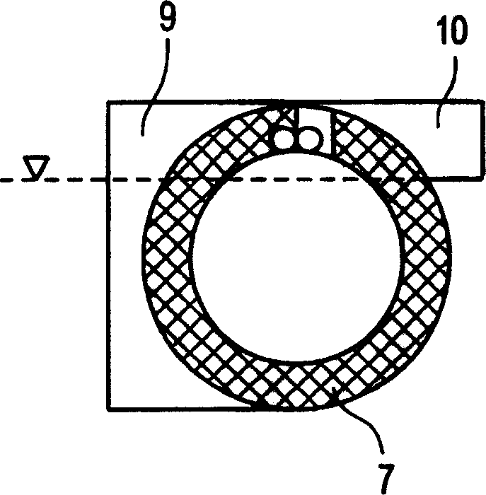
[0022] However, unlike the prior art, according to figure 1 The reducer has an annular heat exchanger 7 which is arranged along the outer circumference, ie radially outside the working space 5 . In the annular heat exchanger 5 , the working fluid is drawn out of the work space 5 , cooled there, and led back into the work space 5 . As a result, the annular heat exchanger 5 is acted upon on its inner side, ie on its heat absorption side, with working fluid as heat carrier.

[0023] To conduct heat f...


PUM


Abstract

The invention relates to a braking device comprising a stator and a rotor. The rotor and the stator are positioned in relation to one another in such a way and a working medium can be supplied or connected in such a way that during a braking operation a braking moment is transferred from the rotor to the stator when the working medium is supplied or connected. The inventive braking device is characterised by the following: a fan impeller, which can enter into and be disconnected from a drive connection with the rotor by the activation and deactivation of a coupling; the fan impeller is configured and positioned in such a way that it supplies a stream of cooling air to the braking device, when the drive connection with the rotor has been made; the coupling is positioned and supplied with working medium in such a way that the supply or connection and evacuation or disconnection of the working medium automatically activates and deactivates the coupling.

Description


Claims


Application Information

Patent Timeline
Owner VOITH TURBO GMBH & CO KG
Why Eureka
Try Eureka