Method for determining the position of an object in a space

An object and space technology, which is applied in the field of determining the position of objects in space, can solve problems such as time-consuming, and achieve the effect of increasing analysis costs and improving costs

Active Publication Date: 2007-02-14
ISRA VISION SYST AG
View PDF1 Cites 19 Cited by
  • Summary
  • Abstract
  • Description
  • Claims
  • Application Information

AI Technical Summary

Problems solved by technology

[0003] However, this method suffers from the disadvantage that either multiple cameras have to be used and calibrated separately, or the determination of the object's position in space is time-consuming, since multiple images have to be taken from different positions

Method used


Image

  • Method for determining the position of an object in a space
  • Method for determining the position of an object in a space
  • Method for determining the position of an object in a space

Examples


Embodiment Construction

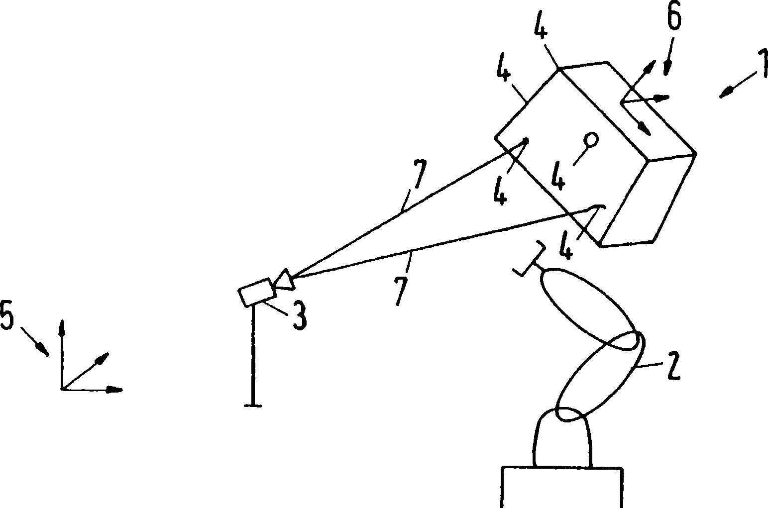
[0025] exist figure 1 A system according to the invention is shown in , with which the method according to the invention for determining the position of an object 1 in space can be carried out. (in the figure) shows an object 1 whose position in space is to be determined. It is often necessary to determine the position of objects in space during production and assembly processes in automatic production lines in which objects 1 are positioned in space, for example by conveyor belts or the like. The position of object 1 is therefore unknown. The purpose of determining the position is usually to be able to carry out a mounting, gripping or machining process on the processing object 1 whose position is unknown. Mounting must generally always take place at the same reference point on the object 1 . In order to achieve this, if the position of the object 1 is unknown, it must be measured and the manipulator 2 , which is to mount the component to be assembled on the object 1 , fol...


PUM


Abstract

The invention concerns a method for determining the position of an object (1) in a space, whereby the measurement parameters (4) of said object (1) are recorded with an optical photographing system (3) calibrated on a spatial system of coordinates (5) and the position of the object (1) in the spatial system of coordinates (5) is determined. In order to be able to determine in reliable manner the position, even with a limited number of photographing devices, it is proposed to detect simultaneously at least two measurement parameters (4) of the object (1) in a photographing device (3) and to use them to determine the position of the object (1).

Description

technical field [0001] The invention relates to a method for determining the position of an object in space, wherein measured features of the object are captured by an optical acquisition device calibrated in a spatial coordinate system, and by means of these measured features the position of the object in space is determined in an image processing device position in the coordinate system. Such methods are used, for example, in production or assembly processes in automatic production lines, in which a machining process is to be carried out on a machining object at an unknown position by means of a handling device. Background technique [0002] In EP 0 911 603 B1 it is described that, in order to optically determine the position of a rigid object in a spatial coordinate system, each of at least three straight lines or edges present on the rigid object is arranged in a plane coordinate system In imaging, the coordinates of these lines or edges are known in the coordinate syst...

Claims


Application Information

Patent Timeline
Patent Type & Authority Applications(China)
IPC IPC(8): G01B11/00G01S5/16B25J9/16
CPCG01B11/002G01S5/163G01B11/005
Inventor S·维南德G·兰伯特
Owner ISRA VISION SYST AG
Why Eureka
Try Eureka