Illuminator, led illuminator, and imaging device with illuminator

A lighting device and imaging technology, applied in lighting and heating equipment, components of lighting devices, lighting devices, etc., can solve the problems of increased waste area, narrow imaging range, waste, etc., and achieve sufficient and uniform illumination Effect

Inactive Publication Date: 2007-02-21
KK TOSHIBA
View PDF1 Cites 27 Cited by
  • Summary
  • Abstract
  • Description
  • Claims
  • Application Information

AI Technical Summary

Problems solved by technology

Rays that do not fall within that rectangle are not utilized and are therefore wasted
In addition, the camera in zoom operation has a narrower imaging field, w

Method used


Image

  • Illuminator, led illuminator, and imaging device with illuminator
  • Illuminator, led illuminator, and imaging device with illuminator
  • Illuminator, led illuminator, and imaging device with illuminator

Examples


Embodiment Construction

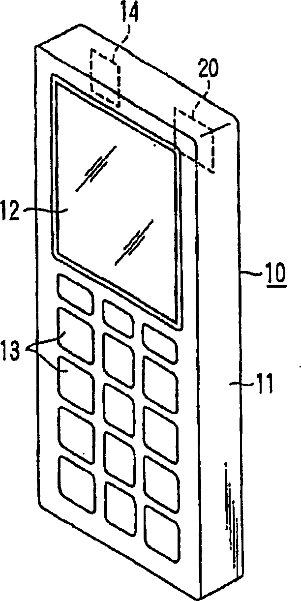
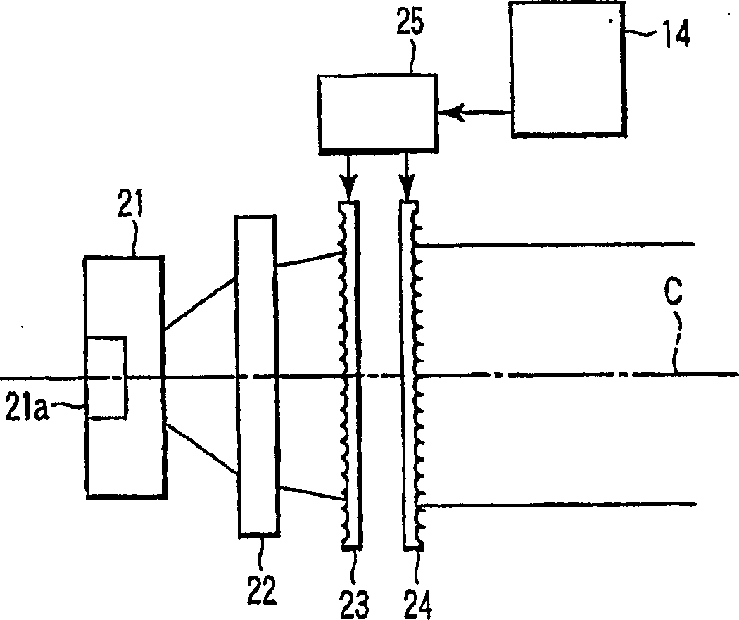
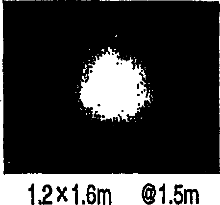
[0037] figure 1 is a perspective view showing a personal digital assistant 10 with a digital camera including the lighting device according to the first embodiment of the present invention. figure 2 is a schematic diagram schematically showing the LED flash 20 included in the personal digital assistant 10 . image 3 is a plan view of the lens arrays 23 and 24 included in the LED flash 20 . Image 6 is a schematic diagram showing the relationship between the illumination area R and the imaging area Q.

[0038] The personal digital assistant 10 has a parallelepiped housing 11 . A display LCD 12 and various operation buttons 13 are arranged on the surface of the casing 11 . On the back of the casing 11 are arranged a CCD camera (imaging device) 14 with a zoom lens and an LED flash (illumination device) 20 .

[0039] Along the optical axis C, the LED flashlight 20 includes in turn: a light emitting module 21; a Fresnel lens 22 made of acrylic material (for example, a resin m...


PUM


Abstract

The invention comprises an imaging mechanism, and an LED illuminator which emits illuminating light to an imaging area of the imaging mechanism. The LED illuminator includes a light emitting module having light emitting elements arranged therein, a Fresnel lens which brings light from the light emitting module into parallel rays of light, a pair of lens arrays arranged in a direction of light coming from the light source, the pair of lens arrays shaping the parallel rays of light produced by the Fresnel lens into a rectangle, and an adjustment mechanism which adjusts an interval between the lens arrays in accordance with an imaging area of the imaging mechanism.

Description

[0001] Cross References to Applications [0002] This application is based on, and claims priority from, the prior Japanese Patent Application No. 2005-236005 filed on August 16, 2005 and the prior Japanese Patent Application No. 2005-370844 filed on December 22, 2005, The entire contents of these patents are incorporated herein by reference. technical field [0003] The present invention relates to an illuminating device used as a light source for a projector, a digital camera, etc., and an imaging device with the illuminating device, and more particularly to an illuminating device designed so that even when an LED having a relatively low output is used as a light emitting element It is also possible to obtain a lighting device having illumination with sufficient illuminance. Background technique [0004] The LED lighting device uses a light emitting module in which a plurality of LED elements (light emitting elements) are mounted on one substrate, and is known to have var...

Claims


Application Information

Patent Timeline
IPC IPC(8): F21S2/00F21V5/04H01L33/00F21W131/403G03B15/03G03B21/14F21K9/60G03B30/00
Inventor 冈田直忠森三树
Owner KK TOSHIBA
Why Eureka
Try Eureka