
Microphone coupler for communication device

A technology for communication equipment and microphones, which can be used in branch office equipment, telephone communication, throat mounting parts of microphones, etc., and can solve problems such as sensor space limitations.

Active Publication Date: 2007-02-21
RES IN MOTION LTD
View PDF0 Cites 11 Cited by
  • Summary
  • Abstract
  • Description
  • Claims
  • Application Information

AI Technical Summary

Problems solved by technology

Locating sensors in a cell phone is a difficult task because of the spatial constraints on the possible locations of the sensors, and within a certain confined space, the location of a sensor such as a microphone must be sufficiently isolated from signal interference generated by other devices in the phone

Method used


Image

  • Microphone coupler for communication device
  • Microphone coupler for communication device
  • Microphone coupler for communication device

Examples


Embodiment Construction

[0026] A portion of the disclosure of this patent document includes material that is subject to copyright protection. The copyright owner has no consent to the reproduction of any patent document or patent disclosure, such as as it appears in the Patent and Trademark Office patent documents or records, but reserves all copyrights whatsoever.

[0027] The following description and the embodiments described herein are provided as illustrations of specific embodiments of the principles of the invention. These examples are provided to illustrate, not to limit, the principles of the invention. In the following description, like parts are designated with like reference numerals throughout the specification and drawings.

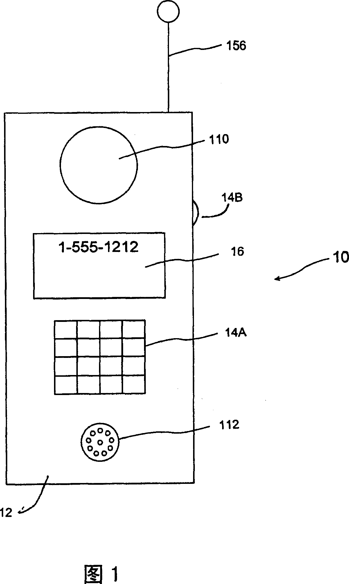
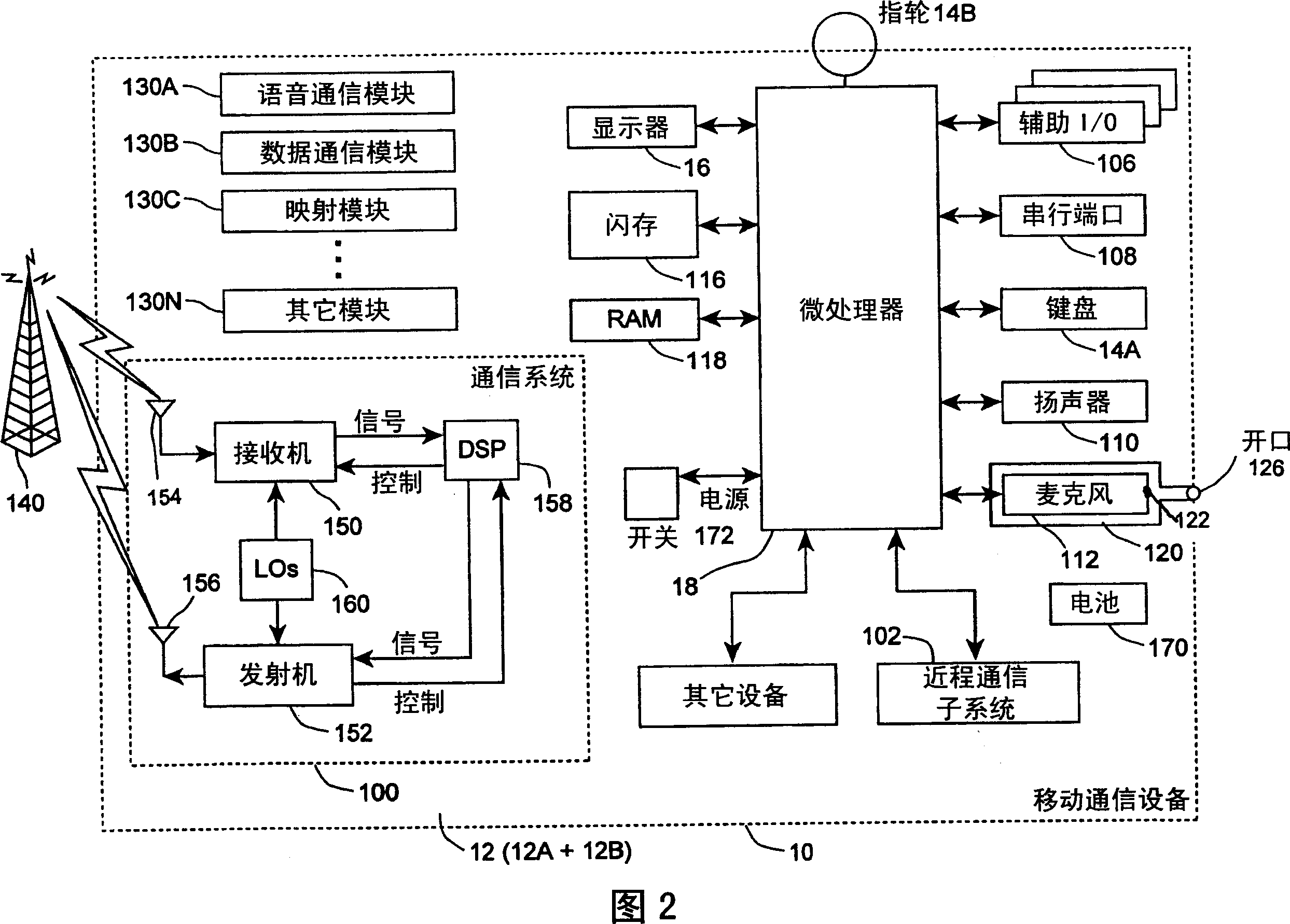
[0028] 1 schematically illustrates a handheld mobile communication device 10 and its components, including a cover 12, an input device (such as a keyboard 14A or thumbwheel 14B) and an output device (display 16), preferably a liquid crystal display (LCD), Althou...


PUM


Abstract

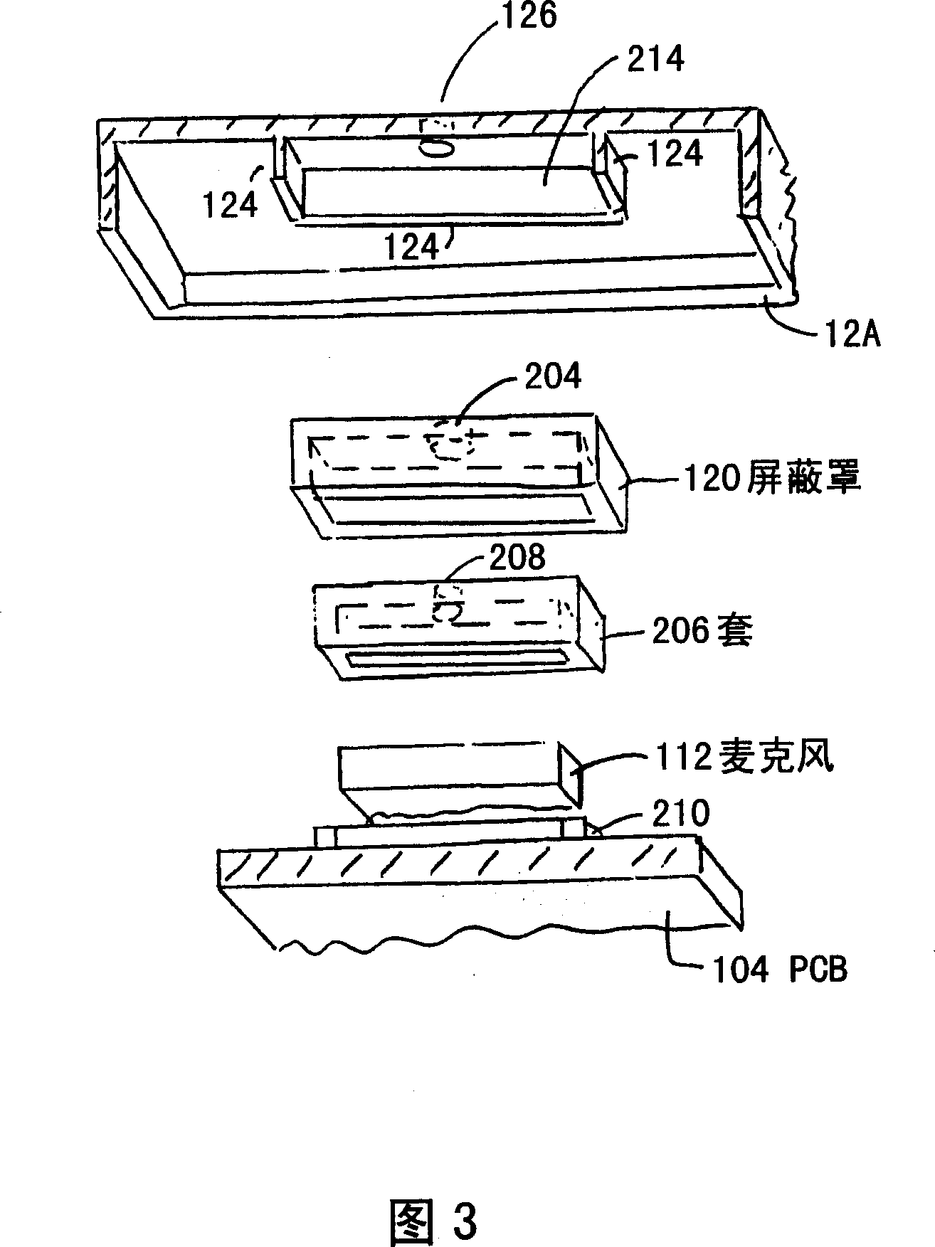
The invention provides a communication device comprising: a cover; a printed circuit board ; a microphone on the printed circuit board; an antenna located at least in part within the cover; and a RF shield can shaped to fit over the microphone about the PCB. In the device , the cover is shaped to enclose the PCB and the RF shield can. The cover provides pressure on the RF shield can to press inward on the microphone to fixedly attach it to the PCB.

Description

technical field [0001] The present invention relates to a microphone coupler for a voice communication device, and more particularly to a coupler that provides an air path from outside the device to a microphone located within the device. Background technique [0002] In a voice communication device, a microphone and speaker must be provided to allow a user to send and receive audio signals with another compatible device used by another person. [0003] In a typical telephone, an earpiece is provided, which is curved and has two sensors, such as a microphone and a speaker, positioned in proper spatial relationship. At the same time, portable communication devices, such as cellular telephones, have smaller and smaller form factors. Locating sensors in a cell phone is a difficult task because of the spatial constraints on the possible locations of the sensors, and within a certain confined space, the location of a sensor such as a microphone must be sufficiently isolated from...

Claims


Application Information

Patent Timeline
Patent Type & Authority Applications(China)
IPC IPC(8): H04B1/58H04B1/04H04R1/14H05K9/00
CPCH04B15/00H04M1/035H04B1/38
Inventor 拉里·霍克乔治·曼科鲁斯罗伯特·菲利普斯
Owner RES IN MOTION LTD
Learn More