Microwave garment for heating and/or monitoring tissue

a tissue heating and/or tissue technology, applied in the field of microwave arrays, can solve the problems of inability to treat the entire lateral extent of disease, difficulty in applying such devices to large areas with complex curvatures, and insufficient microwave applicators for treating many types of superficial tumors

Inactive Publication Date: 2001-12-11
RGT UNIV OF CALIFORNIA
View PDF11 Cites 224 Cited by
  • Summary
  • Abstract
  • Description
  • Claims
  • Application Information

AI Technical Summary

Problems solved by technology

However, difficulties have been encountered in applying such devices to large areas with complex curvatures, such as in the neck and chest area, since the patients must, while retaining the antenna(s) of the microwave applicator in an evenly spaced perpendicular alignment with the surface of the skin, maintain proper inter-antenna spacing in order to facilitate uniform heat treatment.
While previously used microwave applicators operating at either 915 or 433 MHz have demonstrated appropriate penetration of Specific Absorption Rate (SAR) for generating effective heating down to a maximum depth of 1-1.5 cm, treatment of the entire lateral extent of disease is usually impossible due to limited applicator size and poor coupling of the rigid planar structures of previous microwave applicators to the skin surface.
Thus, previous microwave applicators generally have been inadequate for treating many types of superficial tumors, such as chestwall recurrence of breast carcinoma, skin cancer, psoriasis, and other skin conditions, due to their large, bulky size as well as their generally inflexible, planar arrangement.

Method used


Image

  • Microwave garment for heating and/or monitoring tissue
  • Microwave garment for heating and/or monitoring tissue
  • Microwave garment for heating and/or monitoring tissue

Examples


Embodiment Construction

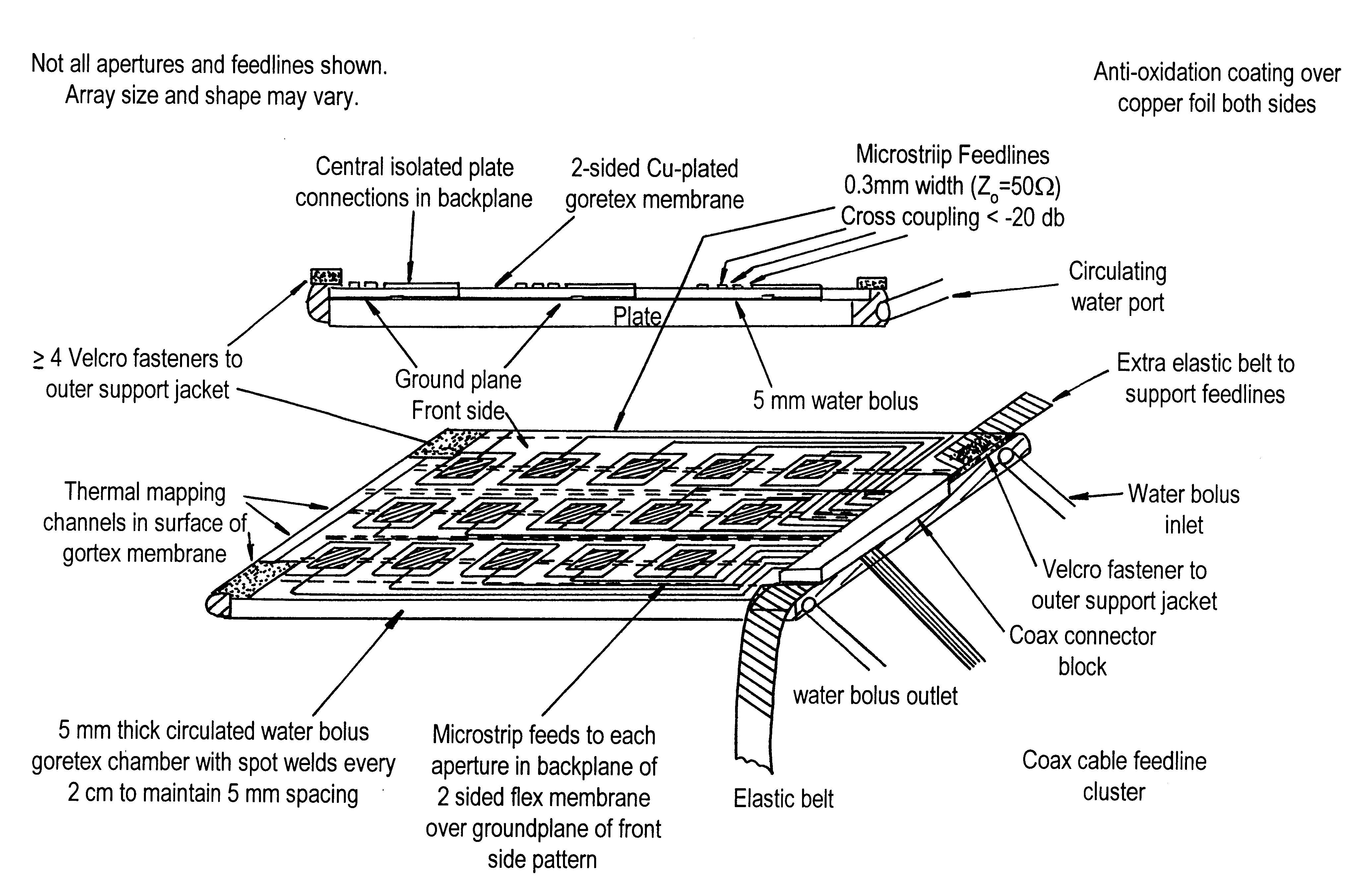
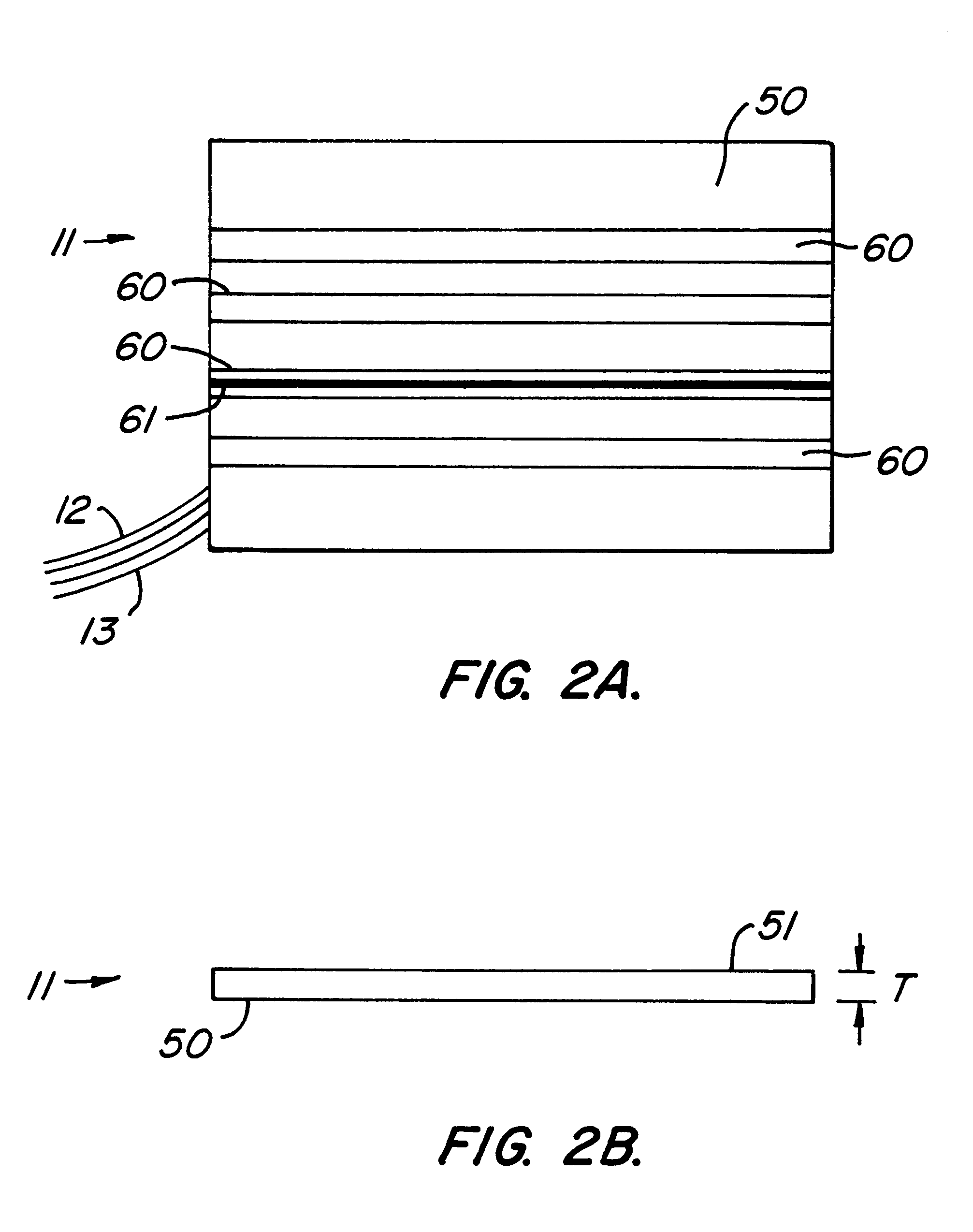
With reference to the drawings, a flexible conformal microwave applicator 10 in accordance with one embodiment of the present invention is illustrated. The applicator includes a flexible dielectric containing compartment 11, commonly referred to as a bolus. Preferably, compartment 11 is comprised of transparent soft and flexible vinyl filled with a fluid dielectric. Preferably two hoses 12 and 13 extend to the housing to provide a flow of water, or other dielectric fluid, which serves as a coolant and temperature control for both the applicator 10 and a surface (e.g. tissue) being heated by the applicator. The dielectric could be a non-fluid but flexible dielectric, such as gels, powders, or plastics, which would provide coupling to the surface but not necessarily cooling.

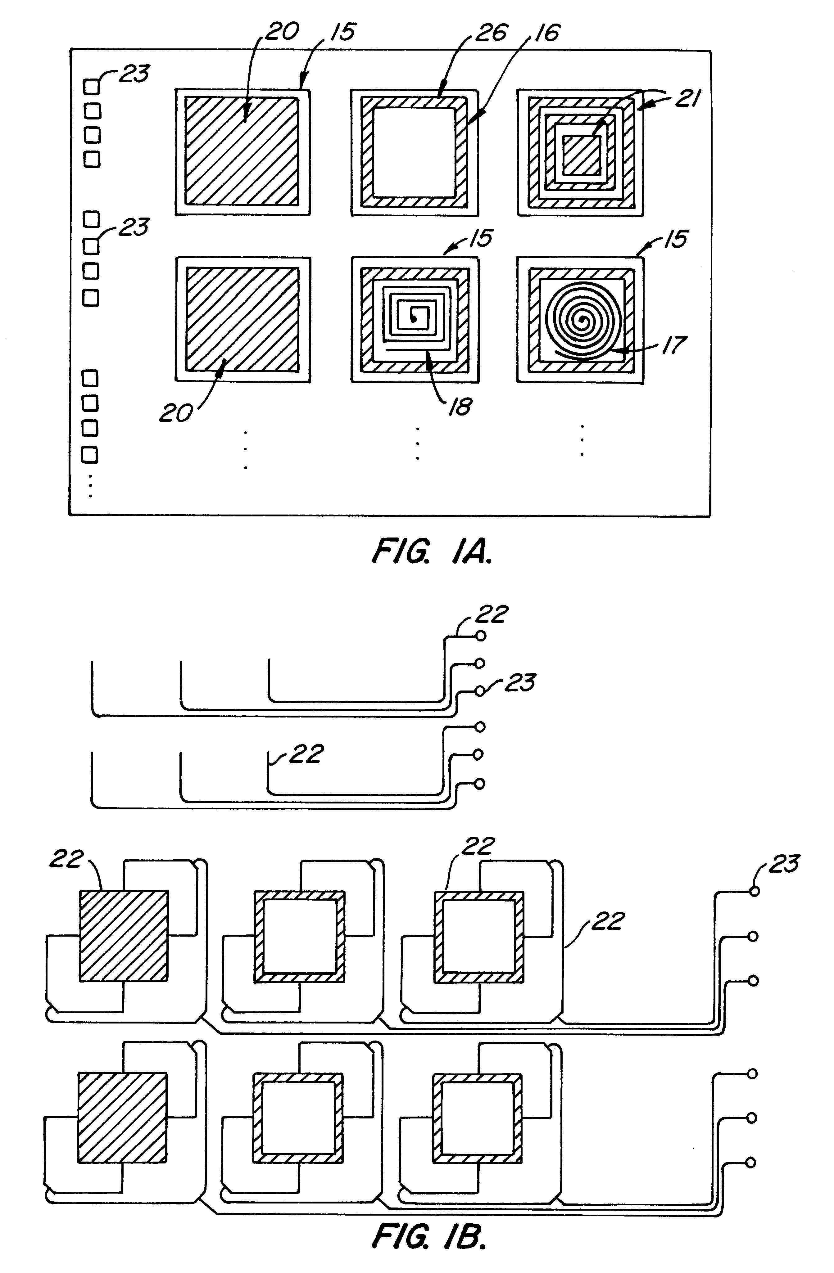
Microwave applicator 10 further includes at least one flexible, printed circuit board (PCB) 14. PCB 14 includes at least one dual concentric conductor aperture (DCC aperture) 15 antenna on the front surface of the ...


PUM


Abstract

A flexible microwave applicator and method of use thereof. The applicator includes a flexible, dielectric-containing compartment (e.g. temperature regulated water or oil) having a variable contour, tissue-engaging surface and an opposite non-tissue-engaging surface and an antenna array adjacent to a non-tissue-engaging surface. The antenna array includes at least one flexible printed circuit board having a front metal surface, a dielectric substrate, a back metal surface, a connection structure for connecting the antenna array to at least one external microwave device, at least one dual concentric conductor aperture on the front surface, and at least one microstrip feedline in communication with the dual concentric conductor aperture and the connection structure. The microwave applicator also includes flexible attachment material for placement over the antenna array and dielectric compartment to allow the microwave applicator to be attached to a subject like a garment which closely conforms to the anatomy portion to be heated. The flexible attachment material may be configured such that the microwave applicator is configured as an appropriately-shaped type of garment, for example, a vest, jacket, cap, hood, blanket, custom shaped conformal wrap, sleeve, or as a pair of shorts.

Description

1. Field of the InventionThe present invention relates generally to applying microwaves to a material, and more particularly, to a flexible microwave array that can conform closely to complex curvatures of the human body for uniform heat treatment of superficially located tumors or benign skin conditions.2. Description of the Prior ArtThe use of microwave applicators for hyperthermia treatment of superficial tumors is well known. However, difficulties have been encountered in applying such devices to large areas with complex curvatures, such as in the neck and chest area, since the patients must, while retaining the antenna(s) of the microwave applicator in an evenly spaced perpendicular alignment with the surface of the skin, maintain proper inter-antenna spacing in order to facilitate uniform heat treatment. Generally, these microwave applicators are capable of heating areas of superficial tissue for treatment of skin and superficial tissue related diseases such as chestwall recur...

Claims


Application Information

Patent Timeline
Patent Type & Authority Patents(United States)
IPC IPC(8): A61N5/02
CPCA61N5/02A61B5/015A61B5/0507A61B2562/046
Inventor STAUFFER, PAUL R.
Owner RGT UNIV OF CALIFORNIA
Why Eureka
Try Eureka