

Seat reclining device
A reclining and seat technology, applied in the field of seat reclining devices, can solve the problems of high cost, high working stress, large radial size and the like
- Summary
- Abstract
- Description
- Claims
- Application Information
AI Technical Summary
Problems solved by technology
Method used
Image

Examples
no. 1 approach
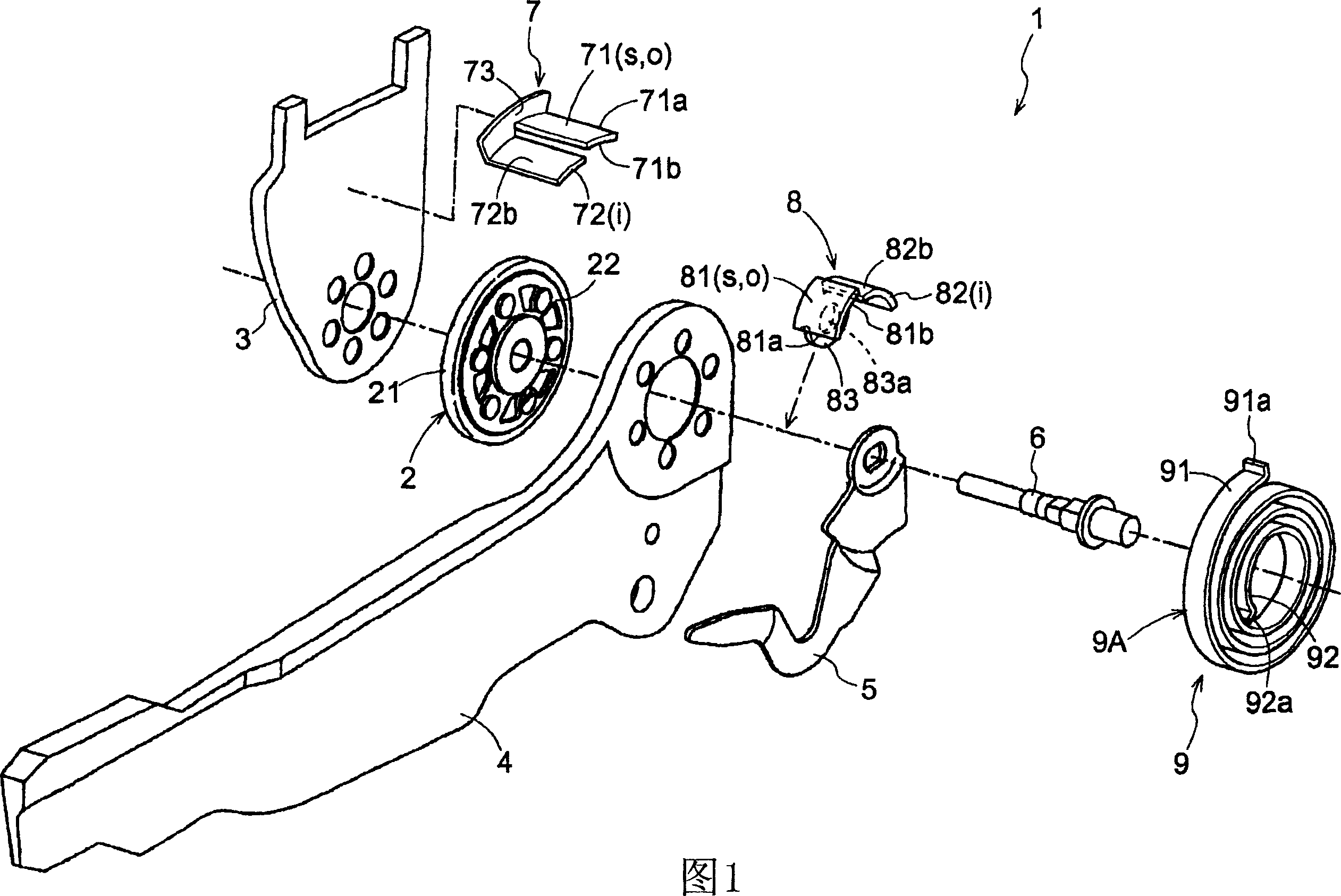
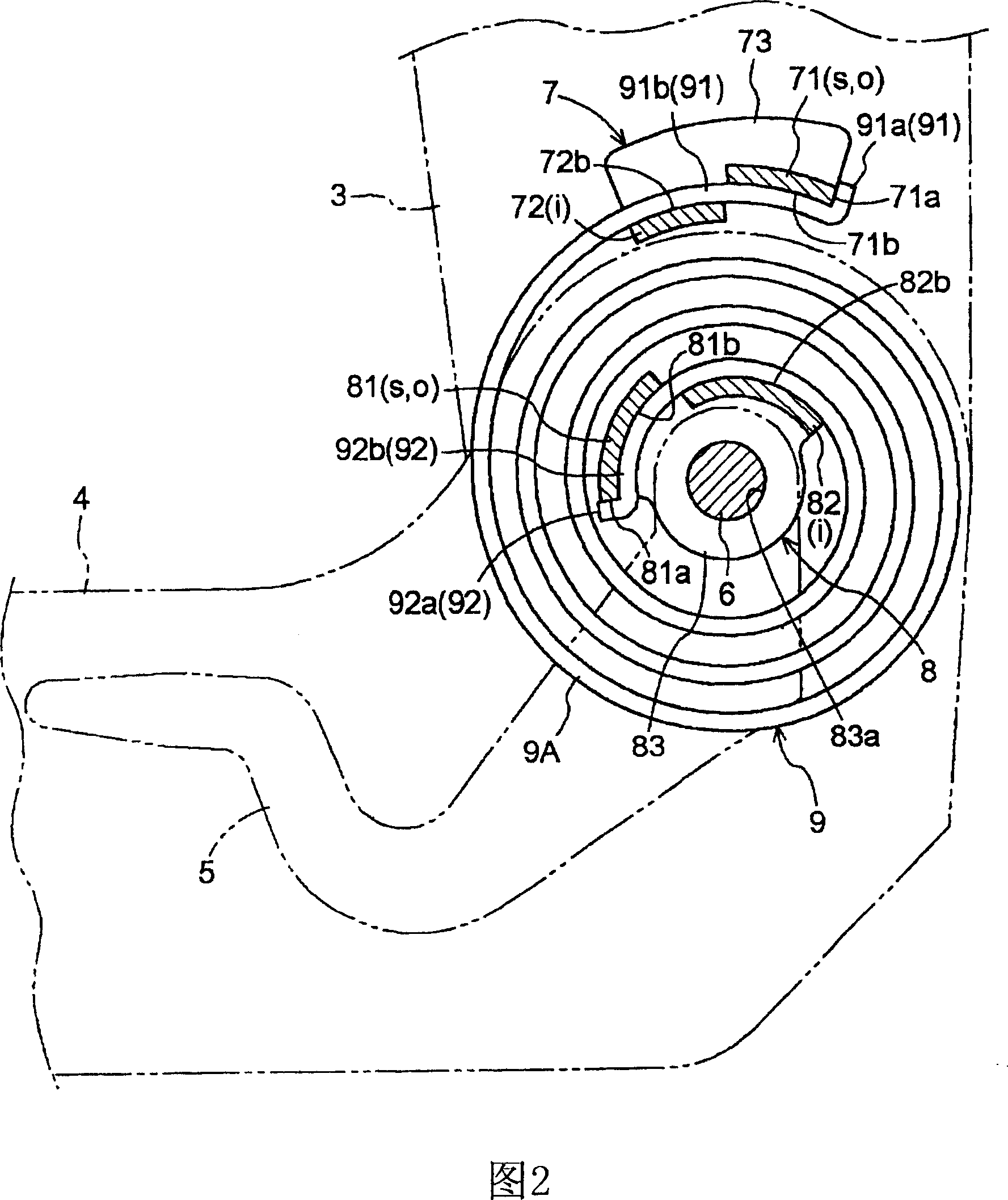
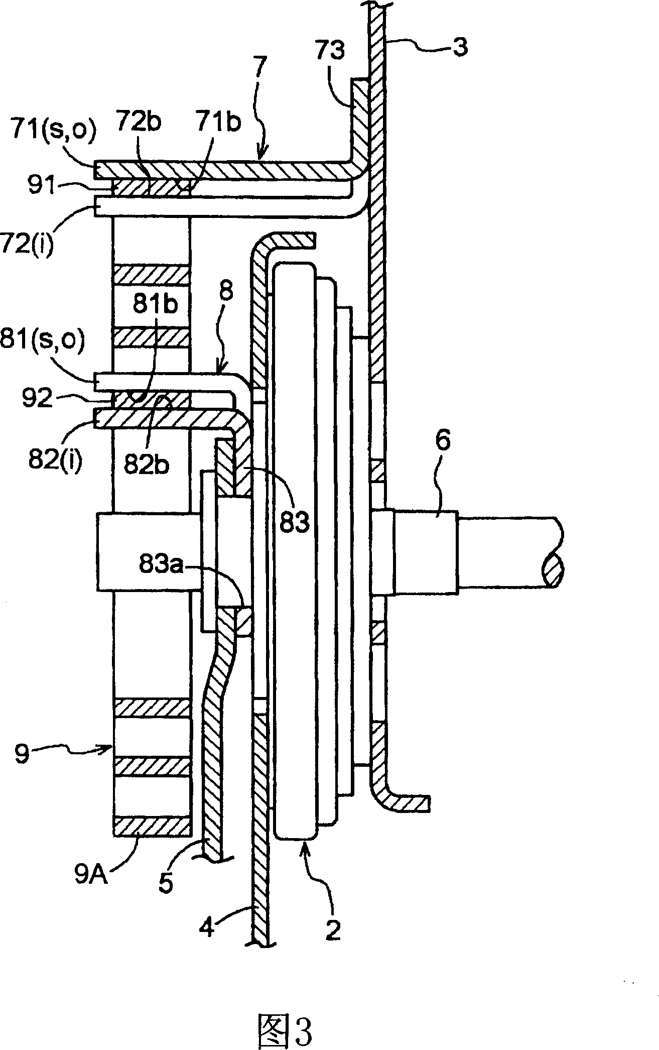
[0022] A first embodiment of the present invention will be explained below based on the drawings. In this embodiment, one example of the seat reclining device 1 attached to a vehicle seat will be described. FIG. 1 shows an exploded perspective view showing a seat reclining device 1 of this embodiment. FIG. 2 is a front view showing the seat reclining device of this embodiment. FIG. 3 shows a cross-sectional view showing the seat reclining device of this embodiment.
[0023] As shown in FIGS. 1 to 3 , the seat reclining device 1 includes a seat back frame 3 , a seat cushion frame 4 , a lock device 2 , an operating lever 5 and a lever shaft 6 . Specifically, the seat back frame 3 constitutes the skeleton structure of the seat back, the seat cushion frame 4 constitutes the skeleton structure of the seat cushion, and the lock device 2 is provided at the joint between the seat back frame 3 and the cushion frame 4 to operate The lever 5 and the lever shaft 6 serve as an operating...
no. 2 approach
[0071] A second embodiment related to the present invention will be explained below based on the drawings. FIG. 4 shows a front view of the seat reclining device 1 related to the second embodiment. As shown in FIG. 4 , the seat reclining device 1 in the second embodiment has basically the same configuration as that of the first embodiment, but the shape of the outer end engaging portion 91 and the inner end engaging portion 92 of the coil spring 9 , the engaging outer The configuration of the outer end engaging piece 7 of the end engaging portion 91 is different from that of the inner end engaging piece 8 engaging the inner end engaging portion 92 . In this section, the seat reclining device 1 of the second embodiment will be explained focusing on the difference between the first embodiment and the second embodiment.
[0072] In the second embodiment, the coil spring 9 includes a stepped portion formed at a substantially middle portion of the outer end joint portion 91 in the...
no. 3 approach
[0098] A third embodiment of the present invention will be explained below based on the drawings. FIG. 5 shows a front view of the seat reclining device 1 related to the third embodiment. As shown in FIG. 5 , the seat reclining device 1 of the third embodiment has substantially the same configuration as that of the first embodiment, however, the outer support plate 71 of the outer end joint 7 and the inner end joint 8 , the outer support plate 81. The inner support plate 72 and the inner support plate 82 are not formed into a plate shape. In the third embodiment, instead of plates, outer support pins 76 and 86 and inner support pins 77 and 87 formed in a pin shape are used. In this section, the seat reclining device 1 of the third embodiment will be explained focusing on the difference between the first embodiment and the third embodiment.
[0099] The outer end fitting 7 includes an outer support pin 76 , an inner support pin 77 and a main portion 73 . Specifically, the ou...
PUM
 Abstract
Description
Claims
Application Information