Image encoding method and image decoding method

An image encoding and decoding method technology, applied in image communication, television, electrical components, etc., can solve the problem of increasing the amount of code, and achieve the effect of reducing the amount of code, high image quality, and high practical value

Inactive Publication Date: 2007-02-28
PANASONIC CORP
View PDF1 Cites 44 Cited by
  • Summary
  • Abstract
  • Description
  • Claims
  • Application Information

AI Technical Summary

Problems solved by technology

However, this high-resolution component is coded image data (difference image) after all, and there is a problem that the amount of code generated by coding increases.

Method used


Image

  • Image encoding method and image decoding method
  • Image encoding method and image decoding method
  • Image encoding method and image decoding method

Examples


Embodiment 1

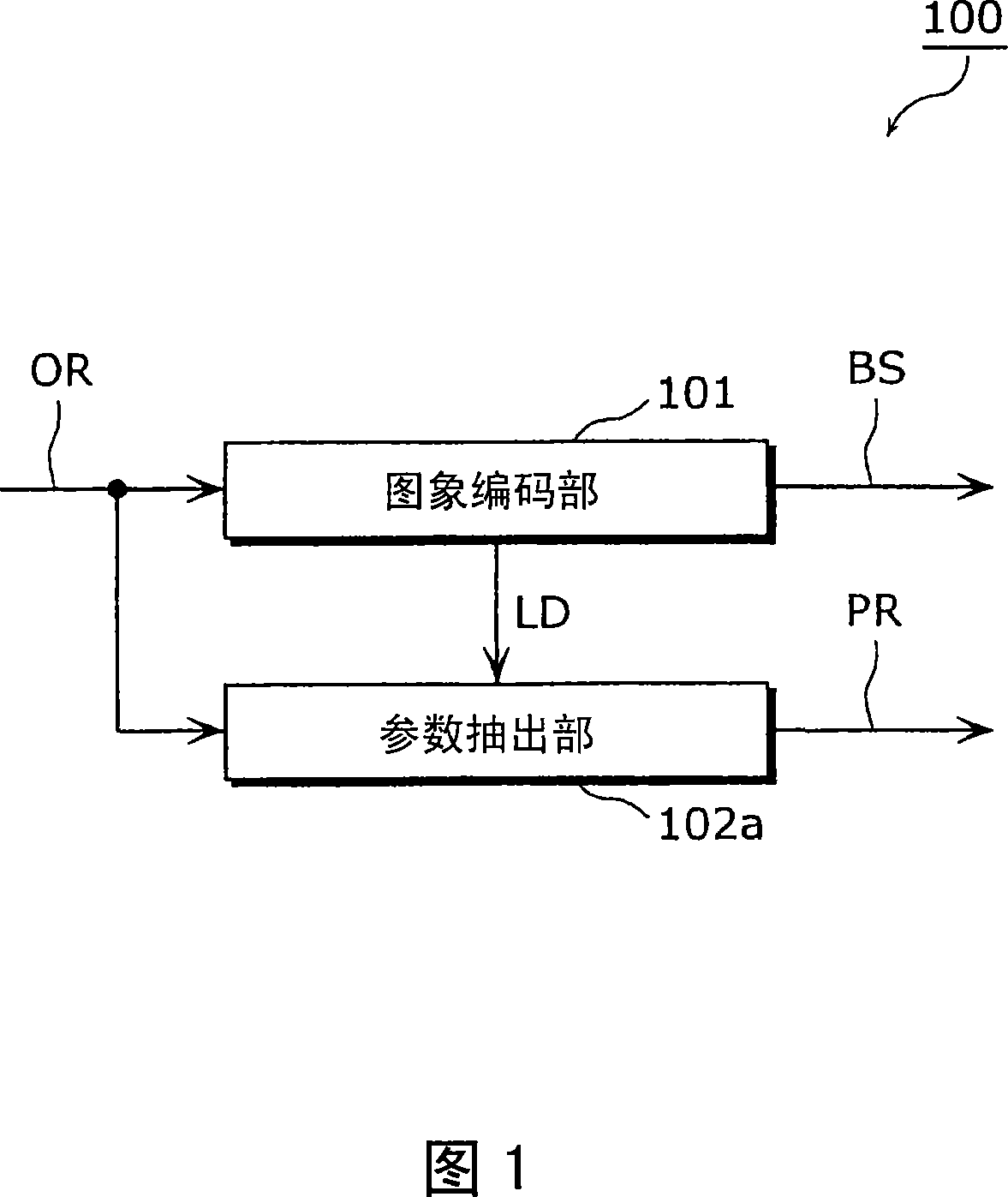
FIG. 1 is a block diagram of an image encoding apparatus 100 using an image encoding method according to Embodiment 1 of the present invention. As shown in FIG. 1, the image encoding device 100 has an image encoding unit 101 and a parameter extraction unit 102a.

[0024]

The input image OR is input to the image coding unit 101 . The image encoding unit 101 encodes an input image OR in accordance with an image encoding method prescribed by a standard. As the image coding method specified by the standard, JPEG (Joint Photographic Experts Group) method of ISO / IEC standard, MPEG (Moving Picture Experts Group) method, H.26x method of ITU-T standard, etc. can be used. The code sequence BS obtained by encoding the input image OR and the local decoded image LD obtained by decoding the encoded input image OR are output from the image encoding unit 101 . The code string BS is output to the outside of the image coding apparatus 100, and processed such as transmission and storage.

[...

Deformed example 1

Here, Modification 1 of the method of generating the image quality improvement parameter PR will be described.

[0045]

The parameter extracting unit of the image decoding device according to this modified example performs discrete wavelet transform instead of discrete cosine transform to generate image quality improvement parameters PR.

[0046]

FIG. 6 is a block diagram showing a configuration example of a parameter extraction unit in this modification.

[0047]

The parameter extraction unit 102 b has discrete wavelet transform units 501 and 502 and an extraction unit 503 . The discrete wavelet transform unit 501 performs discrete wavelet transform on the input image OR, and outputs discrete wavelet transform coefficients OW. The discrete wavelet transform unit 502 performs discrete wavelet transform on the local decoded image LD, and outputs discrete wavelet transform coefficients LW. When performing discrete wavelet transform, the input image OR and the full frame o...

Deformed example 2

Here, Modification 2 of the method of generating the image quality improvement parameter PR will be described.

[0060]

The parameter extracting unit of the image encoding device according to this modified example extracts edge components instead of discrete cosine transform to generate image quality improvement parameters PR.

[0061]

FIG. 8 is a block diagram showing a configuration example of a parameter extraction unit in this modification.

[0062]

The parameter extraction unit 102c includes Laplacian generation units 701 and 702 and an extraction unit 703 . The Laplacian generator 701 generates the Laplacian image OLP from the input image OR, and the Laplacian generator 702 generates the Laplacian image LLP from the local decoded image LD. . When the Laplacian image is generated, the whole frame of the input image OR and the locally decoded image LD can be processed. Or divide the screen into regions and process each region. In this case, there is a method of di...


PUM


Abstract

An image coding method and an image decoding method for improving the quality of a decoded image while significantly reducing the amount of bits are provided. This image coding method includes: a coding step (S102) of coding an input image and generating a bit stream including the coded input image; a decoded image generation step (S104) of generating a decoded image by decoding the coded input image; and a parameter generation step (S106 and S108) of performing frequency-based processing on at least one of the input imagegenerating a parameter for making the decoded image more closely resemble the input image, based on the processing.

Description

technical field [0001] The present invention relates to an image encoding method and an image decoding method for compressing moving images. Background technique [0002] A conventional image encoding device (for example, refer to Patent Document 1) has first and second encoding units, and encodes an image by a hierarchical moving image encoding method. The first encoding unit reduces and converts an input image (high resolution image) into a low resolution image, and encodes the low resolution image. The second encoding unit performs encoding on a difference image between an image obtained by expanding the partial decoded image of the low-resolution image obtained by the first encoding unit and an input image (high-resolution image). [0003] That is, in such a conventional method, a high-resolution image of an input image is coded as a differential image between an enlarged partial decoded image of a low-resolution image and the input image. In other words, the dif...

Claims


Application Information

Patent Timeline
Patent Type & Authority Applications(China)
IPC IPC(8): H04N7/30H04N19/60H04N19/102H04N19/119H04N19/136H04N19/14H04N19/176H04N19/196H04N19/33H04N19/587H04N19/59H04N19/625H04N19/63H04N19/80
CPCH04N19/00278H04N19/00818H04N19/00896H04N19/00066H04N19/00563H04N19/00157H04N19/00903H04N19/00545H04N19/117H04N19/14H04N19/176H04N19/46H04N19/48H04N19/63H04N19/82H04N19/85
Inventor 近藤敏志笹井寿郎
Owner PANASONIC CORP
Why Eureka
Try Eureka