Pressing roller holder for stretching structure

A technology of press roller support and double press rollers, which is applied in drafting equipment, spinning machines, textiles and papermaking, etc., can solve the problems of troublesome manufacturing process, and achieve the effect of economical manufacturing cost and simplified processing

Inactive Publication Date: 2007-03-14
MASCHINENFABRIK RIETER AG
View PDF1 Cites 54 Cited by
  • Summary
  • Abstract
  • Description
  • Claims
  • Application Information

AI Technical Summary

Problems solved by technology

Here, the disadvantage of the known pressure roller holder is that its production is very complex and involves many different work steps

Method used


Image

  • Pressing roller holder for stretching structure
  • Pressing roller holder for stretching structure
  • Pressing roller holder for stretching structure

Examples


Embodiment Construction

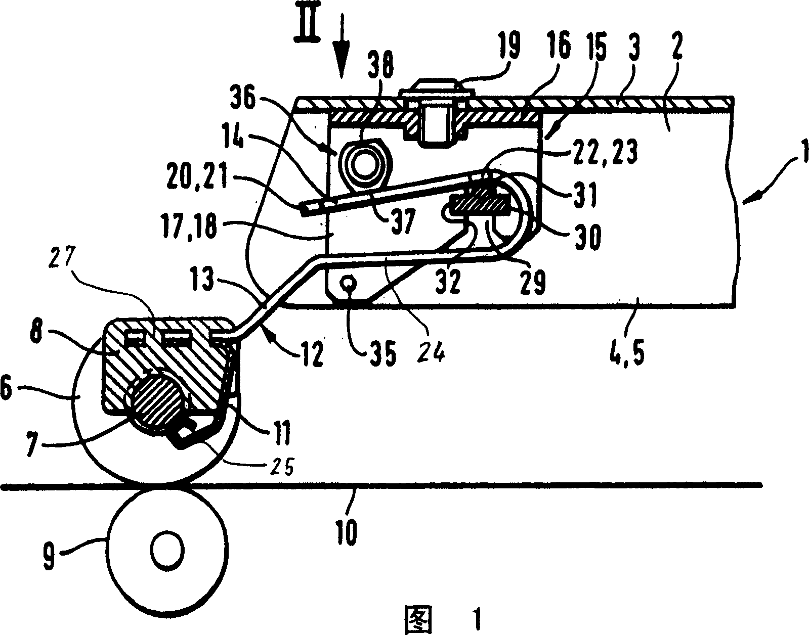
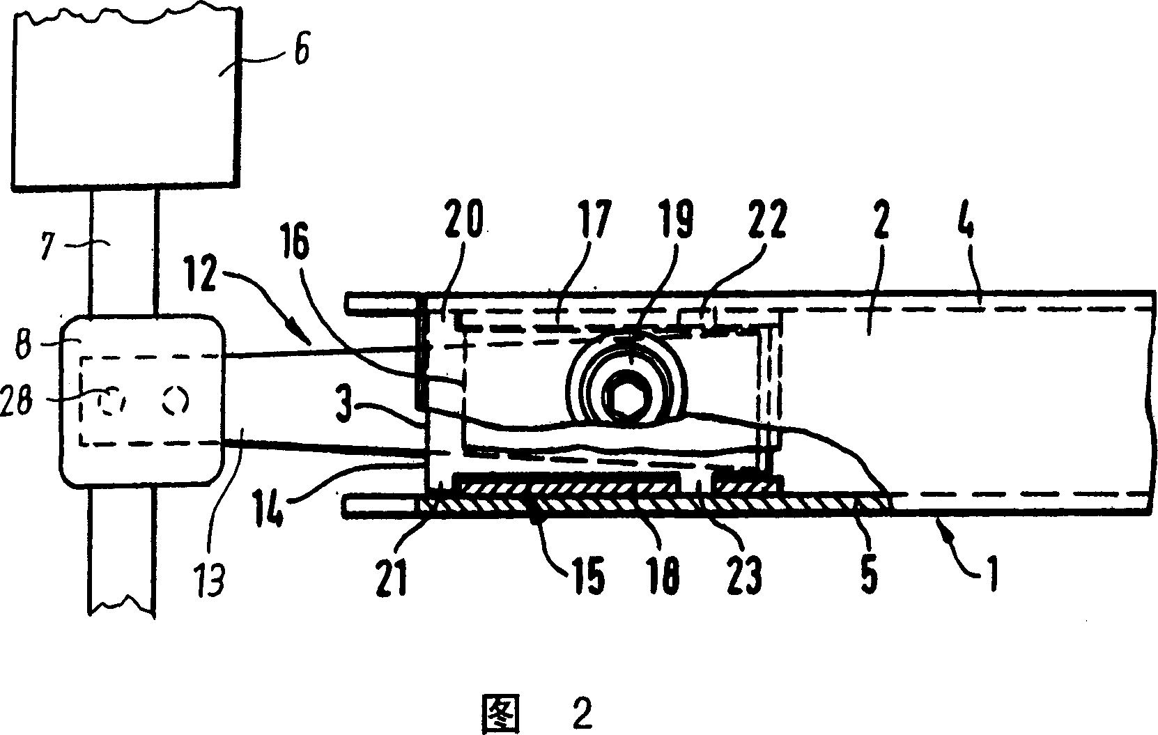
[0016] 1 and 2 partially show a drafting mechanism, in particular a load arm 1 of a drafting mechanism for a ring spinning machine. The load arm 1 has a U-shaped profile 2 . The load arm is supported at its not-shown end on a support rod parallel to the lower rollers of the drafting mechanism, one of which is shown here as the lower roller 9 . The load arm 1 is guided on a support rod and is rigidly constructed such that it can pivot in a plane perpendicular to the lower roller 9 . The load arm 1 supports a plurality of upper rollers in the form of double pressure rollers 6 , of which only one double pressure roller 6 is shown, and which are allocated in corresponding numbers to the lower rollers. The double pressure roll 6 comprises two roller core top rollers which are supported on a common roller shaft 7 and which is clamped between these two roller core top rollers. The fiber strands 10 run between each upper and lower roll 9 of the double pressure rollers 6, and the fib...


PUM


Abstract

The invention relates to a pressure roller support for fixing double pressure rollers in a drafting mechanism, which comprises a spring for pressing the double pressure rollers and a fixing frame for the double pressure roller shafts. The holder is a die-cast or injection-molded part, wherein the holder is cast onto the spring. Furthermore, the invention relates to a method for producing the pressure roller support, in which the spring is inserted into the mold at least in a partial region so that the holder is connected to the spring during the casting process.

Description

technical field [0001] The present invention relates to a pressure roller support for fixing the double pressure rollers in the drafting mechanism, which comprises a spring for pressing the double pressure rollers and a fixing frame for fixing the roller shafts of the double pressure rollers, wherein the The holder is cast as a die-cast or injection-molded part. [0002] Furthermore, the invention relates to a method for producing a roller support for fixing the double pressure rollers in the drafting mechanism, wherein a spring pressing the double pressure rollers is associated with a fixing frame for the roller shafts of the double pressure rollers. connected, and wherein the holder is cast in a mold as a die-cast or injection-molded part. Background technique [0003] Such a pressure roller support is known from DE 38 23 872 A1. In this known pressure roller support, the fastening frame is produced in a known manner as an aluminum die-cast part and is fastened to the sp...

Claims


Application Information

Patent Timeline
Patent Type & Authority Applications(China)
IPC IPC(8): D01H5/50
CPCD01H5/50D01H5/46
Inventor P·布兰肯霍尔恩T·乌诺尔德N·布伦克W·勒纳M·哈特曼K·施蒂姆普夫伦
Owner MASCHINENFABRIK RIETER AG
Why Eureka
Try Eureka