

Circulating fluid bed ash pneumatic control distributing valve
A circulating fluidized bed, pneumatic control technology, applied in fluidized bed combustion equipment, fuel burning in molten state, lighting and heating equipment, etc., can solve the problems of easy jamming, easy wear and high material grade
- Summary
- Abstract
- Description
- Claims
- Application Information
AI Technical Summary
Problems solved by technology
Method used
Image

Examples
Embodiment 1
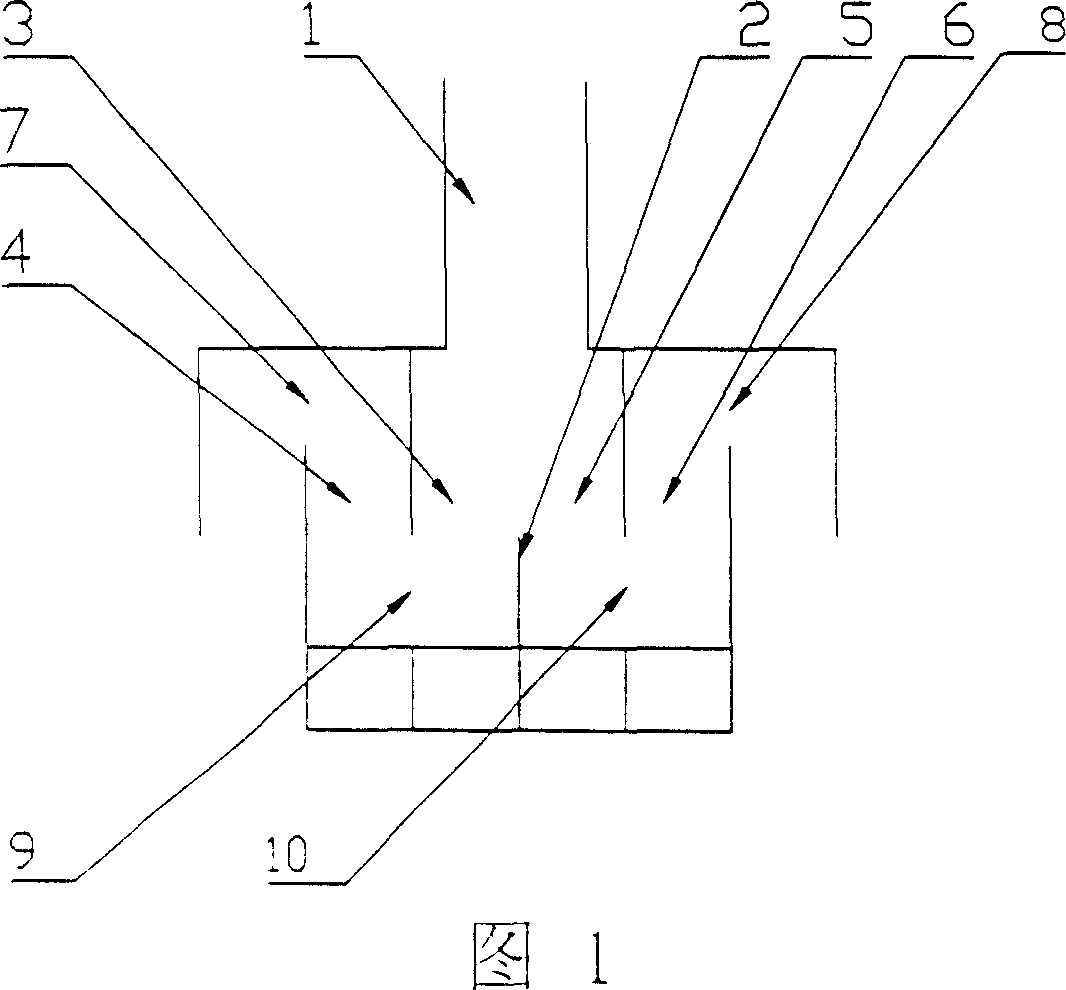
[0022] Fig. 1 is the structural schematic diagram of embodiment 1; As can be seen from the figure, the structure of the circulating fluidized bed circulating ash pneumatically controlled distributing valve of the present embodiment is as follows:
[0023] A vertical splitter plate 2 is arranged directly under the material leg 1 of the high-temperature gas-solid separator of the circulating fluidized bed combustion device, and a first feed chamber 3 and a second feed chamber 5 are respectively arranged on both sides, the upper part of the two chambers is connected, and the bottom surface At the same level, the vertical dividing plate 2 divides the projection of the separator material leg 1 on the bottom surface of the two chambers into two parts; it also includes the first discharge chamber 4 and the second discharge chamber 6; the first feed chamber 3 It communicates with the bottom of the first discharge chamber 4 through the first horizontal hole 9, and the upper part of the ...
Embodiment 2
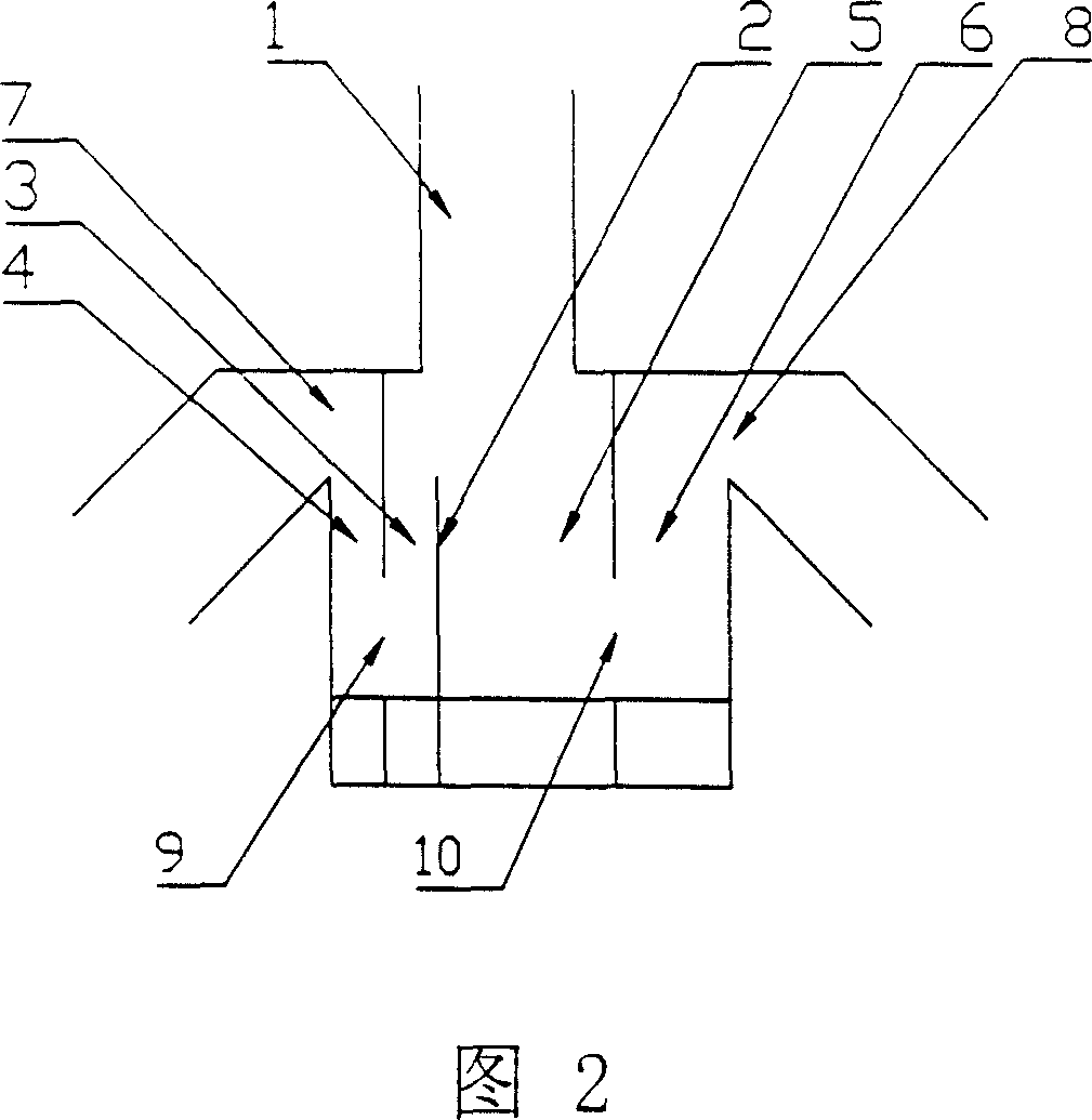
[0025] Fig. 2 is the structural schematic diagram of embodiment 2; As can be seen from the figure, the structure of the circulating fluidized bed circulating ash pneumatically controlled distributing valve of the present embodiment is as follows:
[0026] A vertical splitter plate 2 is arranged directly under the material leg 1 of the high-temperature gas-solid separator of the circulating fluidized bed combustion device, and a first feed chamber 3 and a second feed chamber 5 are respectively arranged on both sides, the upper part of the two chambers is connected, and the bottom surface At the same level, the vertical dividing plate 2 divides the projection of the separator material leg 1 on the bottom surface of the two chambers into two parts; it also includes the first discharge chamber 4 and the second discharge chamber 6; the first feed chamber 3 It communicates with the bottom of the first discharge chamber 4 through the first horizontal hole 9, and the upper part of the ...
Embodiment 3
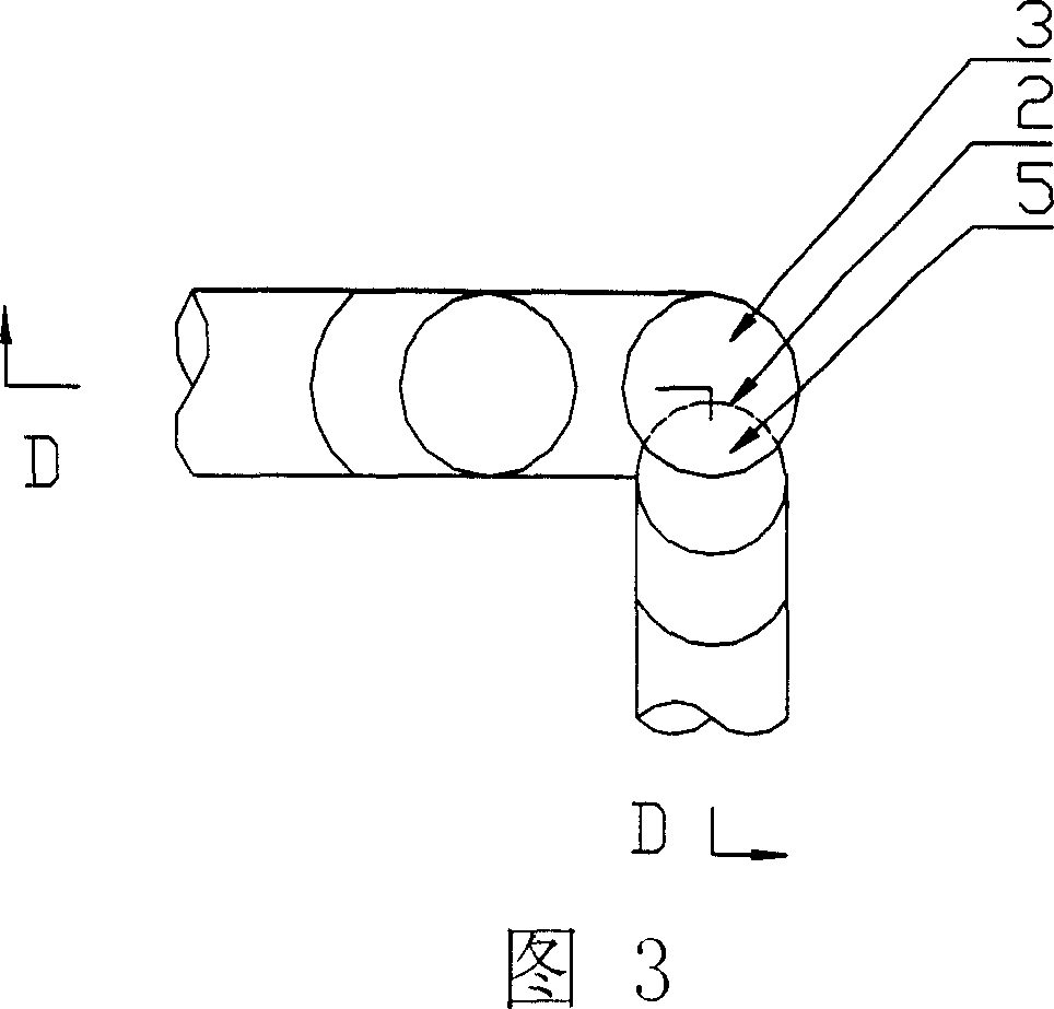
[0028] Fig. 3 and Fig. 4 are the structural schematic diagrams of embodiment 3; As can be seen from the figures, the structure of the circulating fluidized bed circulating ash pneumatic control distribution valve of the present embodiment is as follows:
[0029]The pneumatic control distribution valve is composed of 4 pipe sections, the first pipe section is concentric with the high temperature gas-solid separator material leg 1 of the circulating fluidized bed combustion device, and is located directly below the separator material leg 1, and the second pipe section is connected to the first section The bottom surface of the pipe section is on the same horizontal plane, part of which is located inside the first pipe section, forming a vertical arc-shaped splitter plate 2, which divides the interior of the first pipe section into the first feeding chamber 3 and the second feeding chamber 5, and the upper part of the two chambers The second feed chamber 5 is the part inside the f...
PUM
 Abstract
Description
Claims
Application Information