

External electric supply controllable reactor
A technology of external power supply and reactor, applied in the direction of inductors, variable inductors, variable transformers, etc., can solve problems such as inability to apply high-voltage products and high-voltage power grids, and achieve suppression of system overvoltage and submerged power supply. flow, improve reliability and safety, eliminate the effects of self-excitation
- Summary
- Abstract
- Description
- Claims
- Application Information
AI Technical Summary
Problems solved by technology
Method used
Image

Examples
Embodiment 1
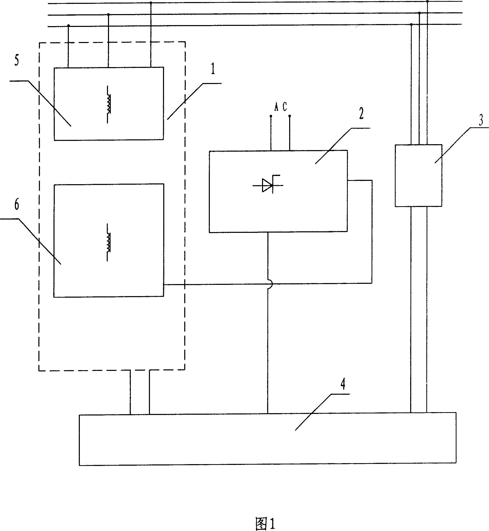
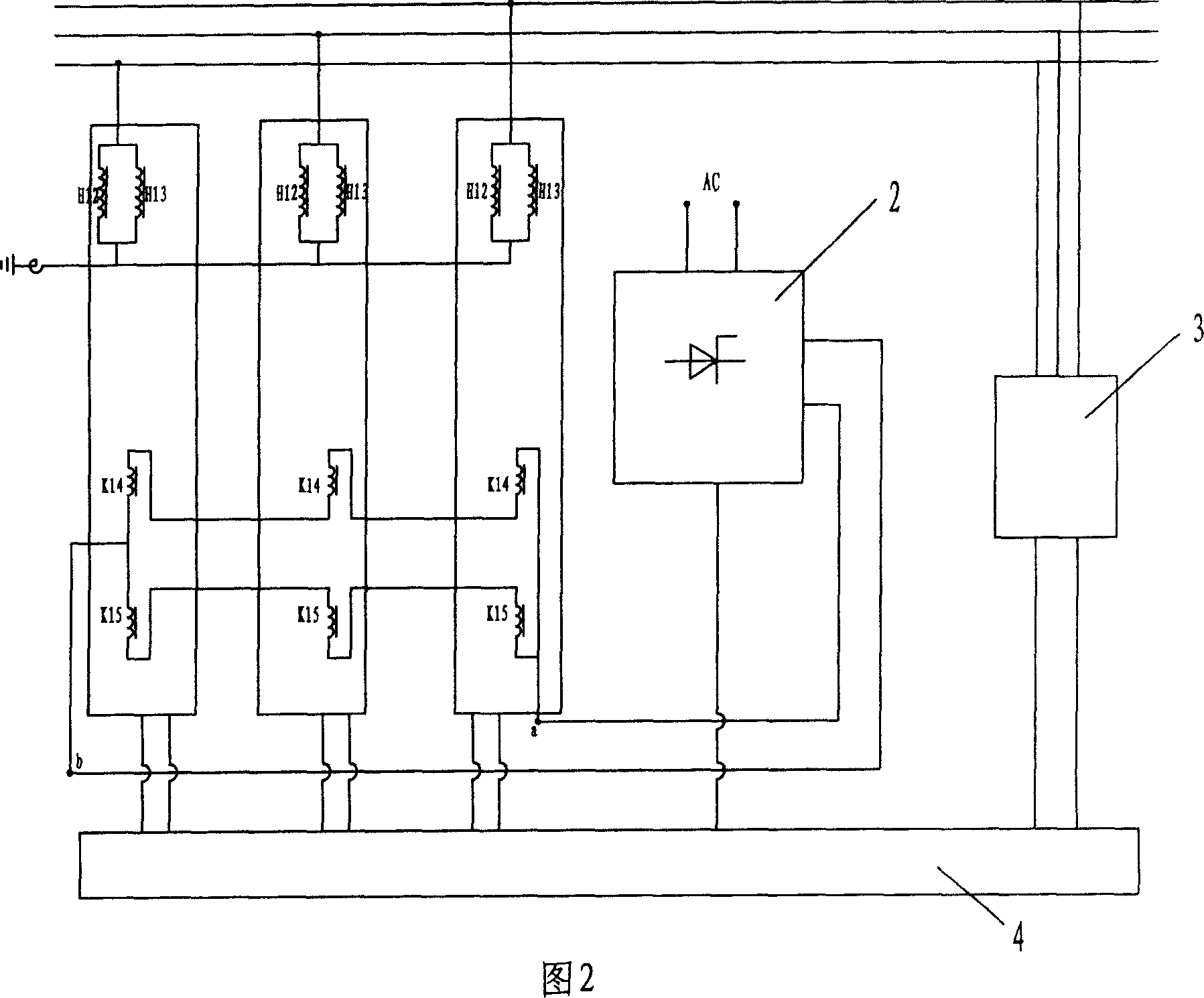
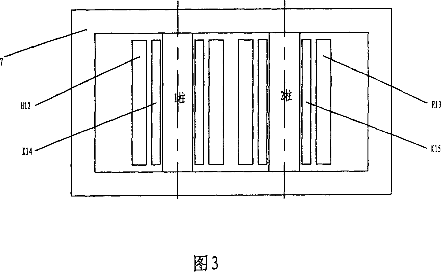
[0040] As shown in Figure 2, it is a three-phase system composed of three single-phase reactors, and the grid side winding in each phase is two sets of coils H 12 、H 13 The group is in parallel structure, and each phase of the control winding has K 14 、K15 Two coils, one group of coils with the same name between phases and phases are connected end to end to form a series branch, and the two branches are then connected in parallel, and the two parallel terminals a and b are respectively connected to the output terminals of the rectification and filtering device. Grid side winding H after three-phase Y connection 12 、H 13 One end is respectively connected to the three-phase transmission line, the other end is connected to a small reactor, and the other end of the small reactor is grounded. The rectifying and filtering device 2 is connected to an external AC power supply, the output terminals of the rectifying and filtering device are connected to terminals a and b of the cont...
Embodiment 2
[0042] As shown in Figure 4, it is a three-phase system composed of three single-phase reactors, each phase of the grid side winding H 12 、H 13 Two coils are connected in series, each phase control winding has two coils K 14 、K 15 A group of coils with the same name between phases and phases are connected end to end to form a series branch, and the two branches are then connected in parallel, and the two parallel terminals a and b are respectively connected to the output terminals of the rectifier and filter device. One end of the three-phase Y-connected grid-side winding is respectively connected to the three-phase transmission line, the other end is connected to a small reactor, and the other end of the small reactor is grounded. The rectifying and filtering device 2 is connected to an external AC power supply, and the thyristor group in the rectifying and filtering device is connected to the control unit 4 . The detection device 3 for detecting power parameters is connec...
Embodiment 3
[0044] As shown in Figure 6, it is a three-phase system composed of three single-phase reactors, and the grid side winding H of each phase 16 Single-coil structure is adopted, and each phase winding of the control winding has two coils K 14 、K 15 A group of coils with the same name between phases and phases are connected end to end to form a series branch, and the two branches are then connected in parallel, and the two parallel terminals a and b are respectively connected to the output terminals of the rectifier and filter device. One end of the three-phase Y-connected grid-side winding is respectively connected to the three-phase transmission line, the other end is connected to a small reactor, and the other end of the small reactor is grounded. The rectifying and filtering device 2 is connected to an external AC power supply, and the thyristor group in the rectifying and filtering device is connected to the control unit 4 . The detection device 3 for detecting power param...
PUM
 Abstract
Description
Claims
Application Information