Self-feeding controllable transductor

A reactor and control winding technology, applied in variable inductors, inductors, variable transformers, etc., can solve the problems that high-voltage power grids cannot be applied, reactors cannot be applied to high-voltage products, etc., to improve reliability and safety. properties, suppressing system overvoltage and latent supply current, and eliminating the effect of self-excitation

Active Publication Date: 2009-12-16
TBEA SHENYANG TRANSFORMER GRP CO LTD
View PDF3 Cites 0 Cited by
  • Summary
  • Abstract
  • Description
  • Claims
  • Application Information

AI Technical Summary

Problems solved by technology

[0002] The research on controllable reactors began in the 1950s, and various types of controllable reactors, such as turn-adjusting type, air-gap adjusting type, high-impedance transformer type, and phase-controlled type, have appeared successively. It has a certain effect, but most of them cannot be applied to the high-voltage power grid. In order to solve this problem, most of the magneto-controlled controllable reactors currently researched have a small section structure on the iron core column, and the coil has a tap. Structured reactors still cannot be used in high voltage products

Method used


Image

  • Self-feeding controllable transductor
  • Self-feeding controllable transductor
  • Self-feeding controllable transductor

Examples


Embodiment 1

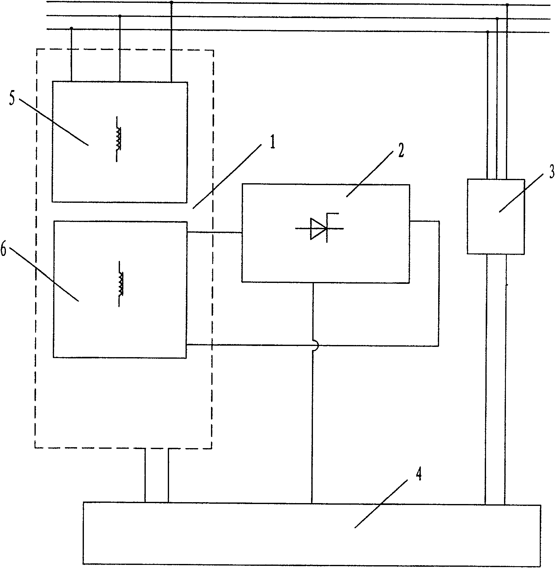
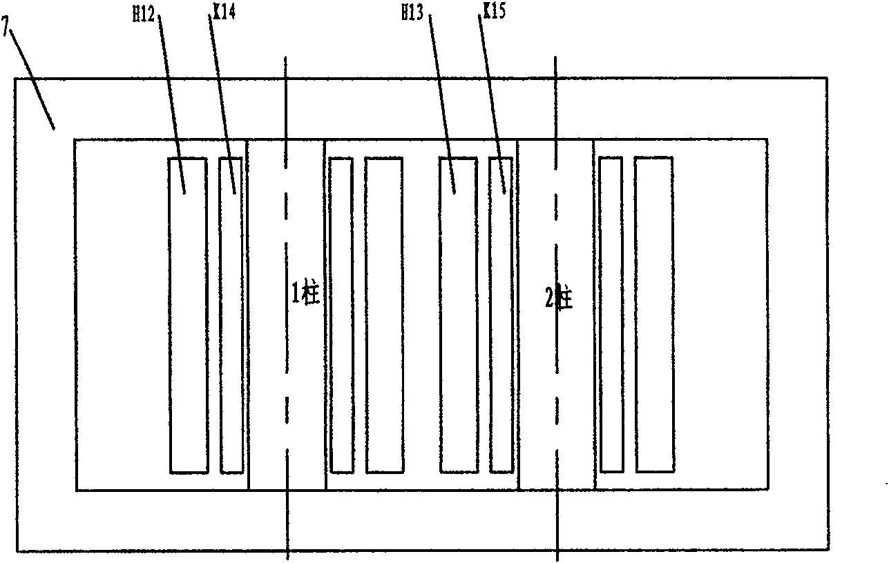
[0040] Such as figure 2 The three-phase system composed of three single-phase reactors is shown, and the grid-side winding H in each phase 12 、H 13The two coils adopt a parallel structure, one end of the three-phase network side winding is connected to the three-phase transmission line, the other end is connected to a small reactor, and the other end of the small reactor is grounded. The three single-phase control winding groups are control windings. Each phase control winding has two coils. The coils of the same name group between phases and phases are connected end to end. The group is a series branch, and the two branches are connected in parallel. The feedback output terminals e and f of the filter device are connected at points, and the induced potentials a and b are taken from the tap ends of the two coils directly connected in series in one phase, and the induced potentials a and b are taken from the upper and lower top taps of the two coils not directly connected in ...

Embodiment 2

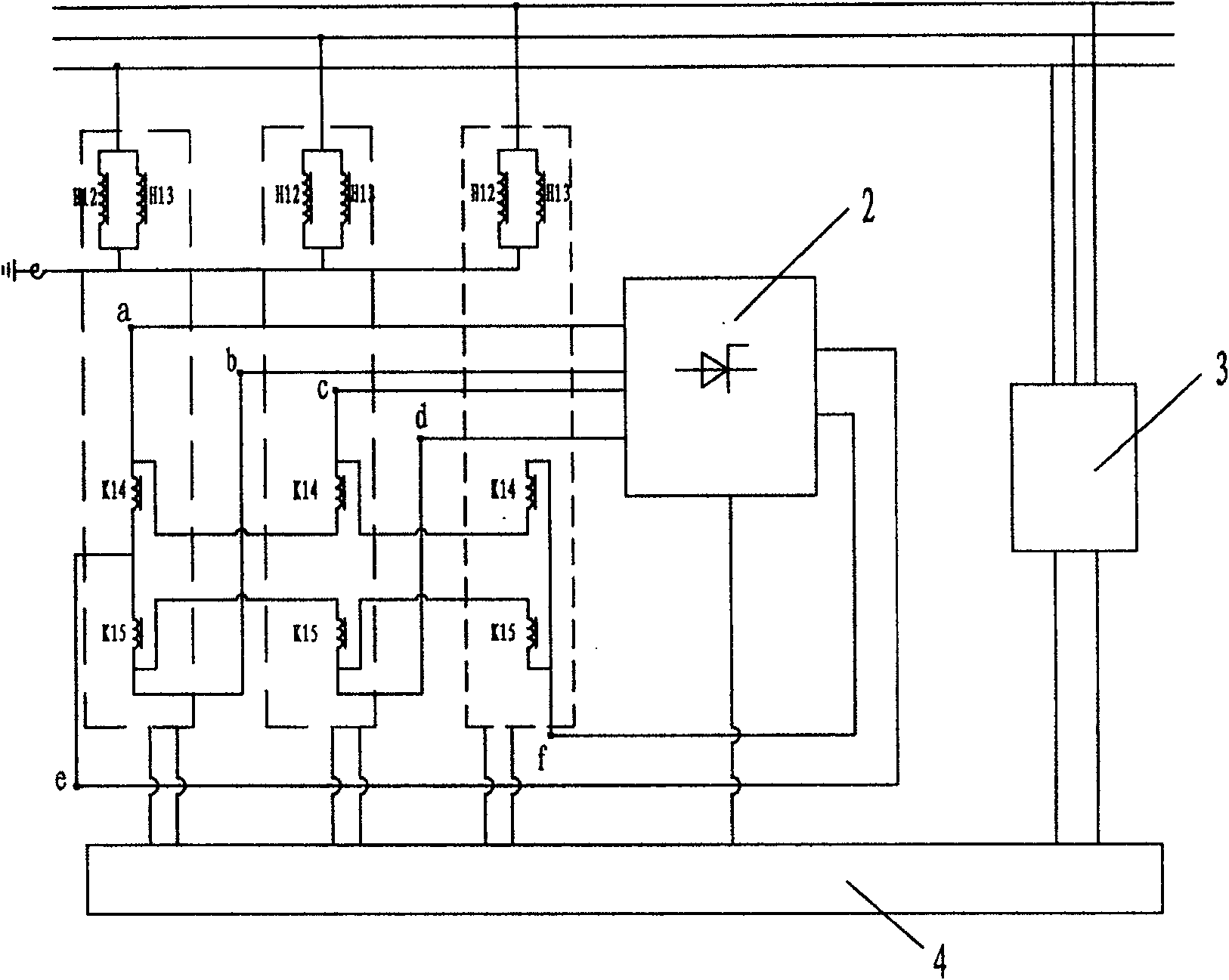
[0042] Such as Figure 4 Shown is a three-phase system composed of three single-phase reactors, each phase grid side winding H 12 、H 13 The structure of two coils in series is adopted, one end of the three-phase network side winding is respectively connected to the three-phase transmission line, the other end is connected to a small reactor, and the other end of the small reactor is grounded. The three single-phase control winding groups are control windings. Each phase control winding has two coils. The coils of the same name group between phases and phases are connected end to end. The group is a series branch, and the two branches are connected in parallel. The feedback output terminals e and f of the filter device are connected at points, and the induced potentials a and b are taken from the tap ends of the two coils directly connected in series in one phase, and the induced potentials a and b are taken from the upper and lower top taps of the two coils not directly conne...

Embodiment 3

[0044] Such as Figure 6 The three-phase system composed of three single-phase reactors is shown, and the grid-side winding H of each phase 16 Single-coil structure is adopted, one end of the three-phase network side winding is connected to the three-phase transmission line, the other end is connected to a small reactor, and the other end of the small reactor is grounded. The three single-phase control winding groups are control windings. Each phase control winding has two coils. The coils of the same name group between phases and phases are connected end to end. The group is a series branch, and the two branches are connected in parallel. The feedback output terminals e and f of the filter device are connected at points, and the induced potentials a and b are taken from the tap ends of the two coils directly connected in series in one phase, and the induced potentials a and b are taken from the upper and lower top taps of the two coils not directly connected in series in the ...


PUM


Abstract

A self-feedback controllable reactor relates to main body that is made up by oil box, magnetic core pole inside of it, left and right side magnet yokes, up and down magnet yokes, winding of magnetic core pole and all kinds of sensor for detecting all species of parameters. It relates to rectifying and filtering equipment, detecting equipment for detecting electrical network parameter and control unit. The net-side winding, compensate winding and control winding set on the magnetic core pole from outside to inside. One end of net-side winding connects with transmit electricity circuitry, and one end of control winding connects with input end of rectifying and filtering equipment and output end of it feedback connects with the other end of control winding to make up of self0feedback control circuit. The control unit joints with end boxes to main body connecting with all kinds of sensor signal, controllable silicon inside of rectifying and filtering equipment and output end of detecting equipment. The input end of control equipment connects with transmit electricity circuitry and changes reactance value and capability of reactor by changing DC current feedback to control winding.

Description

technical field [0001] The invention relates to a reactor, in particular to a self-feeding controllable reactor which can change the reactance value and capacity in a high-voltage power grid. Background technique [0002] The research on controllable reactors began in the 1950s, and various types of controllable reactors, such as turn-adjusting type, air-gap adjusting type, high-impedance transformer type, and phase-controlled type, have appeared successively. It has a certain effect, but most of them cannot be applied to the high-voltage power grid. In order to solve this problem, most of the magneto-controlled controllable reactors currently researched have a small section structure on the iron core column, and the coil has a tap. Reactors with this structure still cannot be applied to high-voltage products. Contents of the invention [0003] Aiming at the problems existing in the prior art, the object of the present invention is to provide a self-feeding controllable r...

Claims


Application Information

Patent Timeline
Patent Type & Authority Patents(China)
IPC IPC(8): H01F29/00H01F27/24H01F27/28H02P13/00
Inventor 安振赵静
Owner TBEA SHENYANG TRANSFORMER GRP CO LTD
Why Eureka
Try Eureka