
Full-jet micro sprinkler head

A micro-sprinkler, full-jet technology, which can be used in spray devices, spray devices with movable outlets, and devices for capturing or killing insects, etc., and can solve problems such as non-declaration of patents

Inactive Publication Date: 2007-03-28
JIANGSU UNIV
View PDF0 Cites 24 Cited by
  • Summary
  • Abstract
  • Description
  • Claims
  • Application Information

AI Technical Summary

Problems solved by technology

[0004] After searching, there is no related patent application

Method used


Image

  • Full-jet micro sprinkler head
  • Full-jet micro sprinkler head

Examples


Embodiment Construction

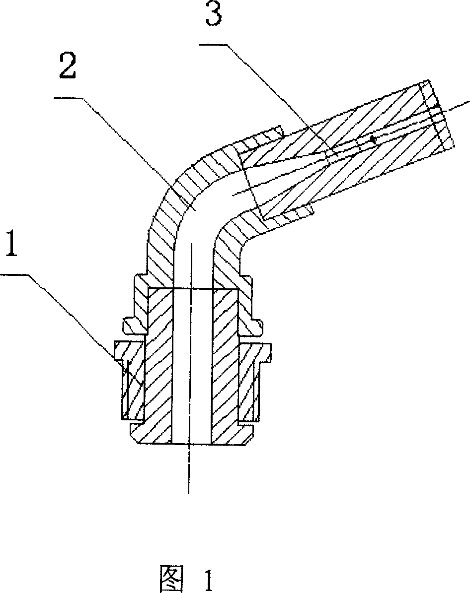
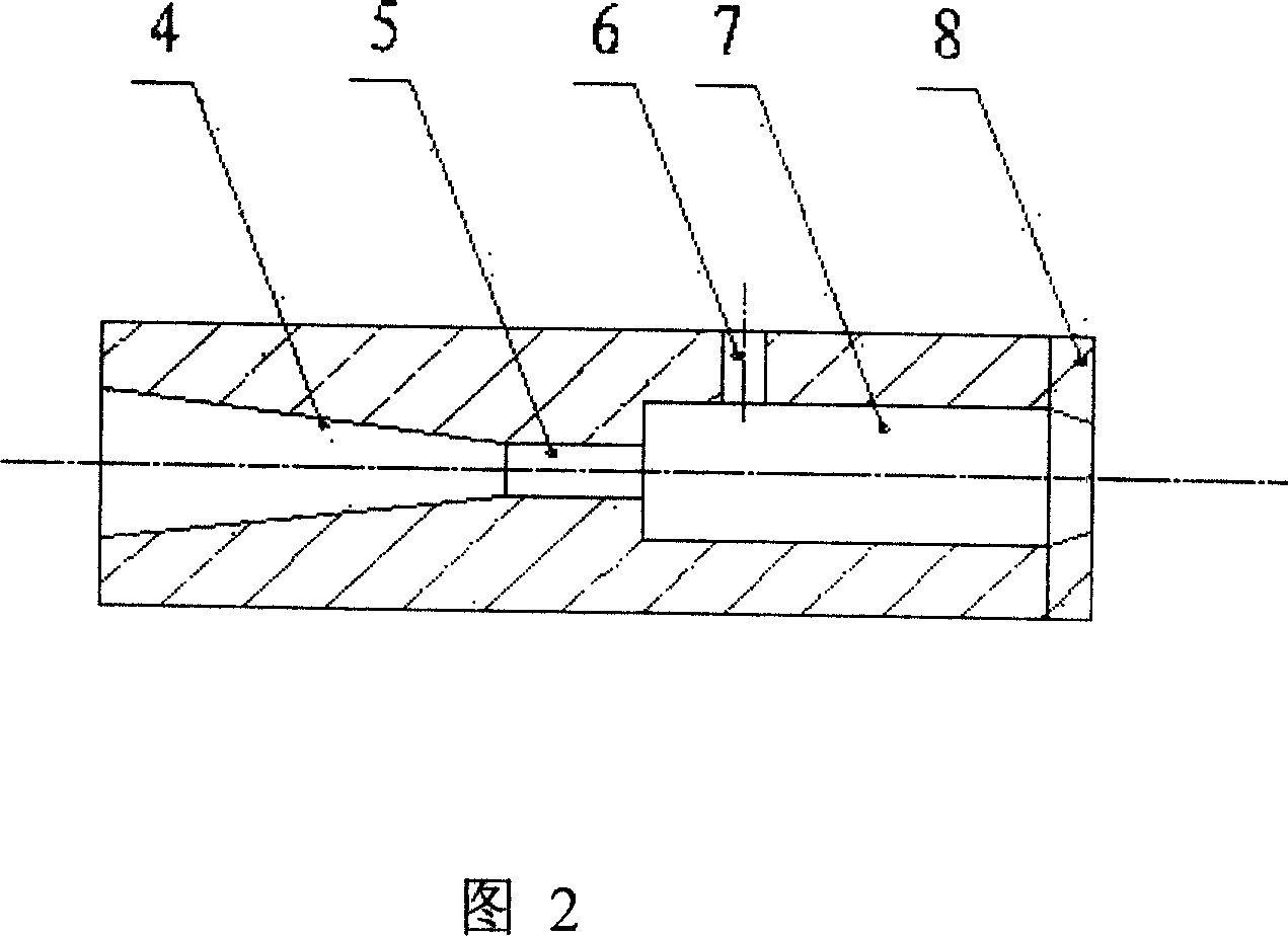
[0011] The full-jet micro-spray head is composed of three parts: a rotary sealing mechanism, a flow channel, and a jet element. The key part of the full-jet micro-spray nozzle is composed of water inlet bell mouth (4), nozzle (5), air supply hole (6), action area (7), and cover plate (8). The water inlet bell mouth, The centers of the nozzle, the action area and the cover plate are on the same axis, and the air supply hole (6) is close to the entrance side of the action area. And the active area (4) is oblong or rectangular, which is combined with an oblong or circular cover plate (8). The water flow enters the action area (7) through the water inlet bell mouth (4) and the nozzle (5), and is sprayed out through the cover plate (8). When the water flow passes through the action area (7), air enters the air supply hole (6), and the water flow deviates to the opposite side of the air supply hole and attaches to the wall. The impact force of the water flow on the side wall of the...


PUM


Abstract

The present invention belongs to a water-saving irrigation key equipment, and it relates to a full-fluidic large-range microsprayer with full-new structure. The key portion fluidic element of said microsprayer is formed from water-feeding bell mouth, nozzle, air-supplementing hole, action zone and cover plate which are connected together. Besides, said invention also provides the concrete working principle of said microsprayer.

Description

technical field [0001] The invention belongs to key equipment for water-saving irrigation, in particular to a full-jet micro-spray head. Background technique [0002] At present, my country's agricultural water consumption accounts for about 80% of the national water consumption. The efficiency of agricultural water use is not high, and water resources are seriously wasted, which further aggravates the lack of agricultural water resources. The irrigation water utilization rate of micro-irrigation can reach more than 90%, which is an advanced water-saving irrigation technology among many water-saving irrigation technologies in the world. The area of ​​micro-irrigation in my country only accounts for 0.5% of the irrigated area, which is not suitable for the development of water-saving agriculture and the adjustment of rural economic structure in my country. With the rapid and large-scale development of my country's water-saving agriculture, a large number of high-quality new ...

Claims


Application Information

Patent Timeline
IPC IPC(8): B05B3/04A01M7/00
Inventor 李红袁寿其刘孟谢福祺陈超朱兴业
Owner JIANGSU UNIV
Learn More