
Pillow

一种枕头、头部的技术,应用在枕头、家里用具、床罩等方向,能够解决头部载置部件塌陷、增加颈部负载、无法充分降低后头部位置等问题

Inactive Publication Date: 2007-03-28
IKEN KOUGYO +1
View PDF1 Cites 11 Cited by
  • Summary
  • Abstract
  • Description
  • Claims
  • Application Information

AI Technical Summary

Problems solved by technology

[0006] However, since the head rest member resists the head load and remains on the raised position suitable for the head of a person in a side-lying position, it is necessary to make the upward direction applied to the head rest member in its raised position. The magnitude of the pressing force is equivalent to the load on the head. Therefore, even if the person becomes a supine position, the head mounting part will not drop with good responsiveness, and this will cause the problem of increasing the load on the neck.
In addition, the above-mentioned conventional pillow does not have a structure in which the headrest part collapses with the load on the head. position, between the head rest member and the bottom member, there will also be a gap of the width of each link member in the up and down direction. The problem that the position of the back of the head cannot be lowered sufficiently when the part is on
In addition, there is also the following problem: since in the above-mentioned conventional pillow, there is always an upward pressing force applied to the head rest member, therefore, in order to lower the position of the head, a person must always resist the pressing force. Relying on force increases the load on the neck, causing shoulder soreness, headache, numbness of hands and feet, neck pain, stiff neck, etc.

Method used


Image

  • Pillow
  • Pillow
  • Pillow

Examples


Embodiment Construction

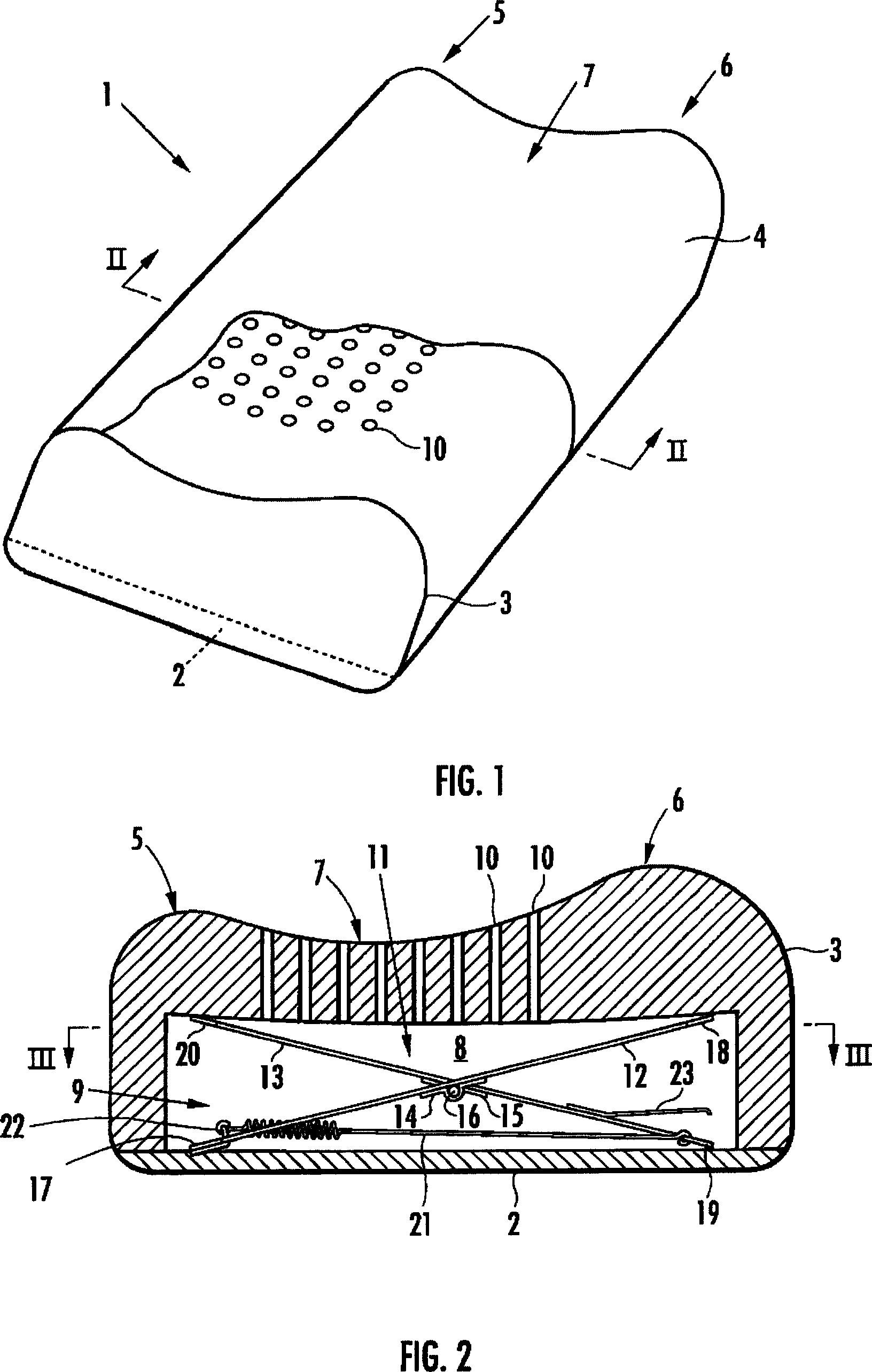
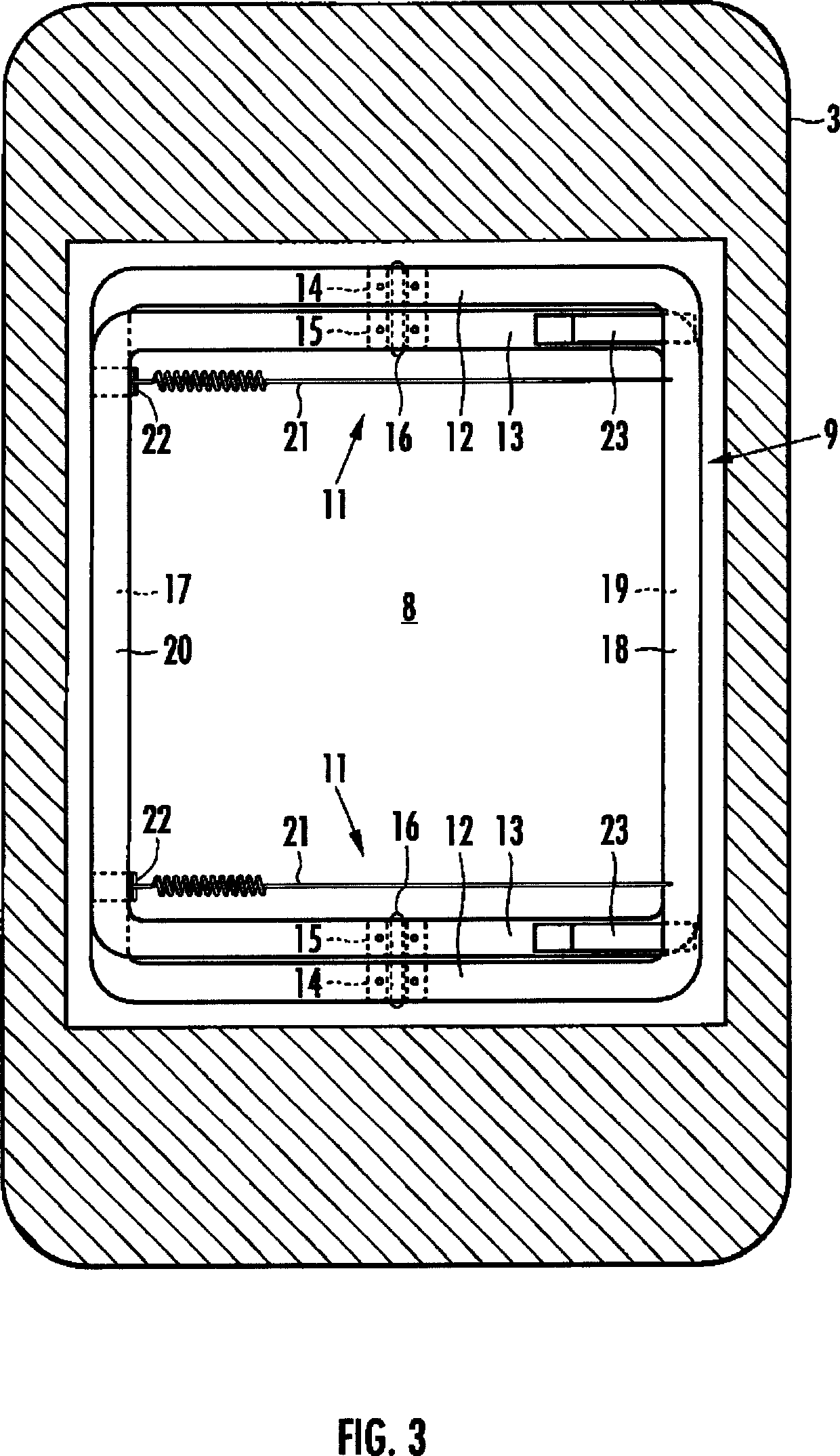
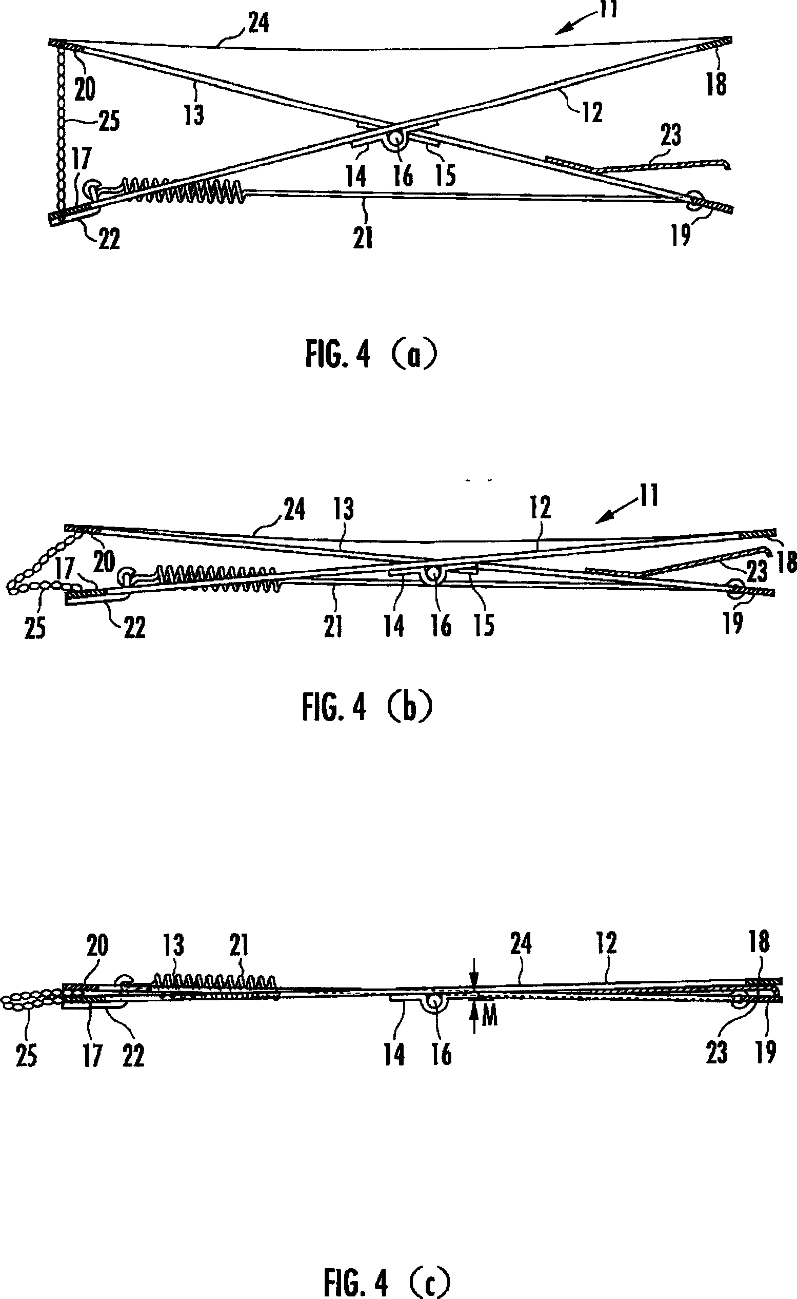
[0042] Hereinafter, embodiments of the present invention will be described with reference to the drawings. 1 is a perspective view of the pillow of the first embodiment of the present invention, FIG. 2 is a cross-sectional view along the line II-II in FIG. 1, FIG. 3 is a cross-sectional view along the line III-III in FIG. 2, and FIG. 4 is a view showing the first embodiment 5 to 7 are cross-sectional views showing the operation of the pillow of the first embodiment.

[0043] As shown in FIG. 1, the pillow 1 of the first embodiment includes a bottom member 2 made of felt or the like and a head mounting member 3 arranged on the bottom member 2, and the bottom member 2 and the head mounting member 3 Covered by outer covering cloth 4. The head mounting member 3 is composed of a molded body made of a low-resilient polyurethane foam, and is formed in a substantially rectangular shape with a horizontally long shape in a plan view. When a person’s head is placed on the head placement memb...


PUM


Abstract

A pillow whose height can be automatically adjusted so that, when a user is in a face-up lying position, the back of the user's head is slightly higher than his or her back, and in addition, whose height can be automatically varied between a face-up lying position and a side lying position. A cavity section (8) is formed in a head placement member (3), and the cavity section (8) sags so that, when the head is placed on the pillow with the face up, the distance between the lowermost section of the head and a bottom member (2) is in the range of 10 - 30 mm. An urging mechanism (9) is placed in the cavity section, and the urging mechanism has X-shaped links (11) arranged in the cavity section (8), separated in the lateral direction. Each of the X-shaped links is constructed by pivotally connecting, by an intermediate link shaft (16), a first link member (12) sloping forwardly upward and a second link member (13) sloping backwardly upward. The urging mechanism further has a front side upper connection member (18) for connecting front end sections of the first members of both X-shaped links to each other, a back side upper connection member (20) for connecting rear end sections of the second link members of both X-shaped links to each other, and a spring member (21) for applying a spring force to both X-shaped links, the spring force acting in the direction that causes both link members of each X-shaped link to approach each other in the forward / backward direction along an action line in the forward / backward direction.

Description

Technical field [0001] The present invention relates to a pillow used as bedding. More specifically, it relates to a pillow whose height changes with the posture during sleep. Background technique [0002] The posture of a person during sleep is the most natural and optimal posture to fall down while staying upright and to become supine. At this time, the back of the head, which is the lowest position in the head, is slightly higher than the back, and the back of the neck is at a position higher than the back of the head by about 10 to 50 mm. Therefore, it is hoped that the pillow used as a bedding can make the position of the back of the head slightly higher than the height of the back when the person is in a supine posture, and at the same time, it can be supported at a position higher than the back of the head with appropriate strength. On the neck. [0003] On the other hand, when a person turns into a side-lying posture by turning over during sleep, the head is supported by ...

Claims


Application Information

Patent Timeline
Patent Type & Authority Applications(China)
IPC IPC(8): A47G9/10
CPCA47G9/1009A47G9/10A47G9/109A47G2009/1018
Inventor 中山慎一郎
Owner IKEN KOUGYO
Learn More