Bar for a warp knitting machine and method of making same

A technology of knitting machine and bar, which is applied in the field of manufacturing knitting machine bar

Inactive Publication Date: 2007-04-04
KARL MAYER TEXTILMASCHFAB GMBH
View PDF9 Cites 8 Cited by
  • Summary
  • Abstract
  • Description
  • Claims
  • Application Information

AI Technical Summary

Problems solved by technology

This especially causes problems if the combs are of longer length

Method used


Image

  • Bar for a warp knitting machine and method of making same
  • Bar for a warp knitting machine and method of making same
  • Bar for a warp knitting machine and method of making same

Examples


Embodiment Construction

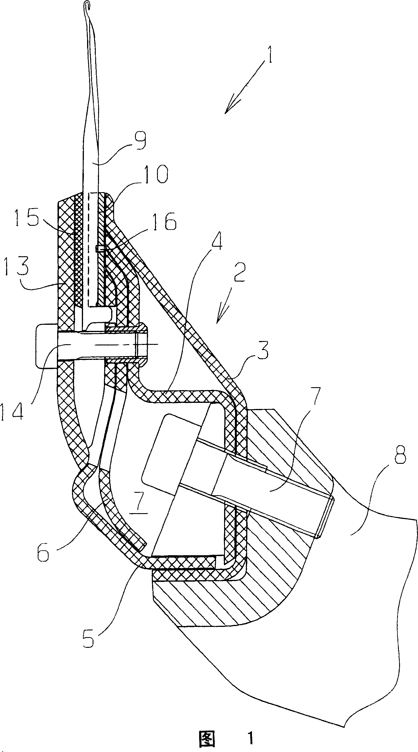
[0034] FIG. 1 shows a hub 1 with a carrier 2 . The support has several profiles 3 , 4 , 5 , 6 . The profiles are connected to one another and surround a cavity 7 . The profiles 3-6 are made of a plastic, in particular a carbon fiber reinforced plastic (CFK). Each profile 3-6 is open and can be made by extrusion.

[0035] The support 2 is fixed on a drive rod 8 of the knitting machine by means of a screw 7 .

[0036] The needle holder 1 supports a plurality of knitting needles 9, of which only one is visible, since the knitting needles 9 are arranged one behind the other perpendicular to the plane of the drawing.

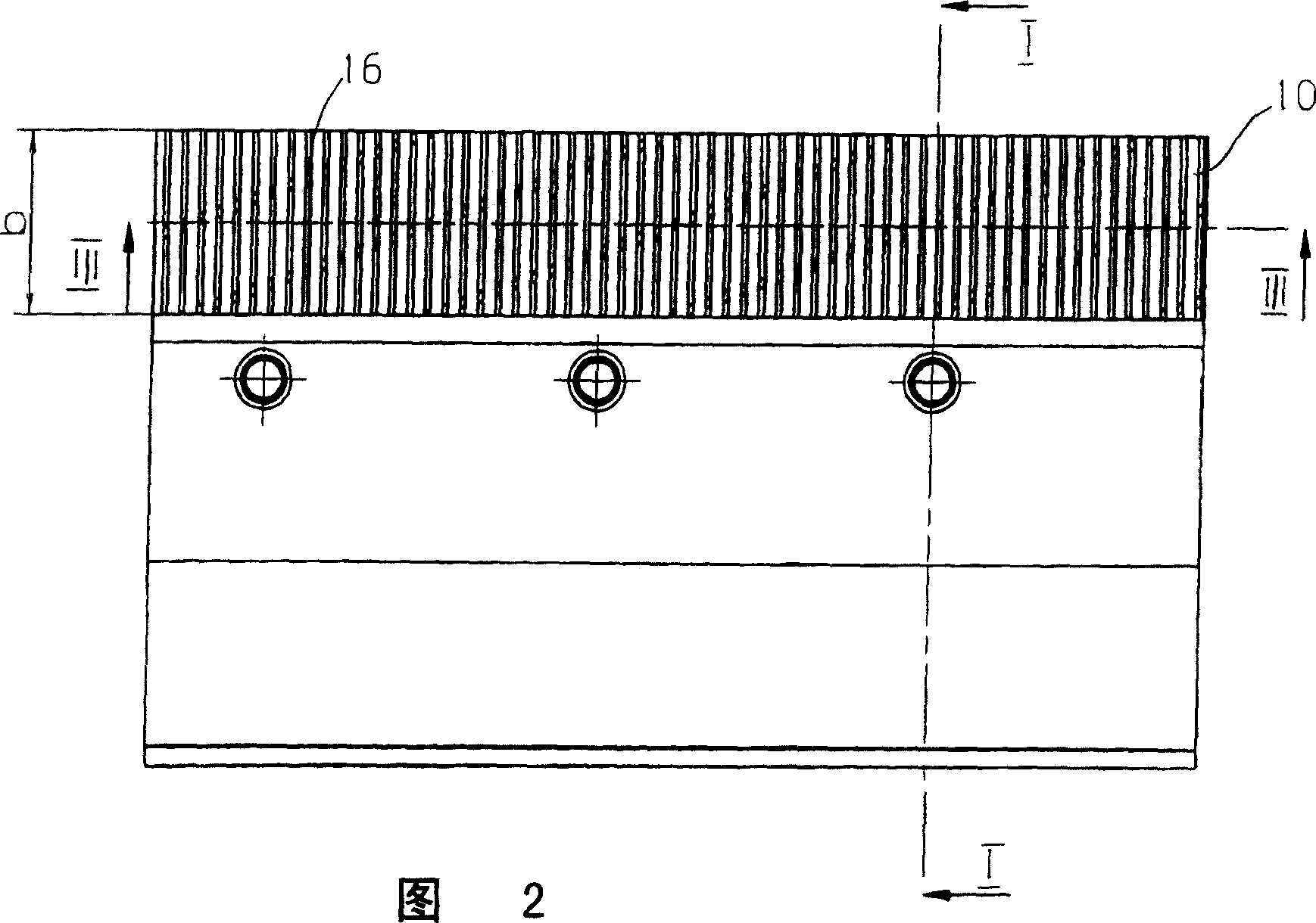
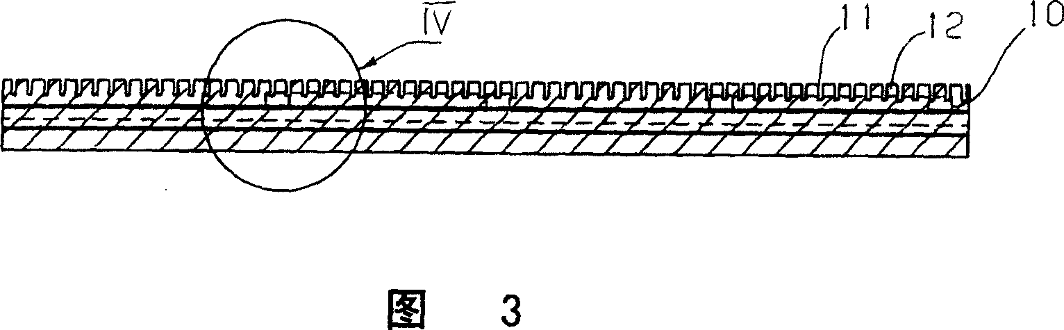
[0037] In this case, the knitting needles 9 are not fastened directly to the support 2 , but are arranged in an auxiliary part 10 which has a plurality of needle grooves 11 which are separated from one another by webs 12 . Each needle groove 11 is used to accommodate a knitting needle 9 . The auxiliary part bears against the support 2 with a fastening surface 19...


PUM


Abstract

The present invention relates to a guide-bar(1)for a warp knitting machine and a method of making the same, wherein the guide-bar(1)for a warp knitting machine has a bracket(2)made of a first material and an accessorial part(10)which is made of a second material and holds a knitting implements(9). The accessorial part(10)is fixed on the bracket(2)by a clamping surface(19). The space precision is anticipant to be kept regardless of temperature as much as possible. Thus the accessorial part(10)has a slot(16)extending along sloping line in the clamping surface(19).

Description

technical field [0001] The invention relates to a knitting machine bar with a support made of a first material and an auxiliary part made of a second material for accommodating a knitting element, wherein the auxiliary part is formed with a The fixing surface is fixed on the bracket. Furthermore, the invention relates to a method for producing a bar of a knitting machine, in which method the auxiliary part is fastened to the support by means of a fastening surface. Background technique [0002] For example, DE 43 02 858 C1 discloses a knitting machine bar of this type and a method for its manufacture. In this case, a plurality of needle slots are provided on the auxiliary part, which extend substantially perpendicularly to the longitudinal direction of the auxiliary part. After the auxiliary part is fixed on the bar, the auxiliary part is divided into individual segments of predetermined length. [0003] DE 103 48 557 B3 discloses a bar of a knitting machine, wherein the ...

Claims


Application Information

Patent Timeline
Patent Type & Authority Applications(China)
IPC IPC(8): D04B27/24
CPCD04B27/06
Inventor K·米斯塔
Owner KARL MAYER TEXTILMASCHFAB GMBH
Why Eureka
Try Eureka