
Substrate test gear

A substrate inspection and substrate technology, which is used in measuring devices, optical testing flaws/defects, instruments, etc., can solve the problems of increasing the distance between the inspected substrate and the backlight, unable to obtain the observed brightness, and backlight lighting scattering, etc., to achieve high efficiency The effect of visual inspection

Inactive Publication Date: 2007-04-04
OLYMPUS CORP
View PDF2 Cites 2 Cited by
  • Summary
  • Abstract
  • Description
  • Claims
  • Application Information

AI Technical Summary

Problems solved by technology

[0004] However, in the substrate appearance inspection device of Patent Document 1, the transmitted illumination unit illuminates from below the swing table, and since the observation direction of the inspector is different from the direction of transmitted illumination, effective transmitted illumination observation cannot be performed.
In addition, there is also a proposed device in which the transmitted illumination unit is fixed on the swing table, and the transmitted illumination device also swings together with the swing table. There is a problem that the size of the substrate to be inspected will increase the size of the drive unit
[0005] In addition, in the substrate inspection device of Patent Document 2, when observation is performed by transmitted illumination at a position behind the moving range of the substrate to be inspected, the distance between the substrate to be inspected and the backlight increases.
[0006] Therefore, especially as the substrate to be inspected increases in size, the illumination of the backlight is scattered, and there is a problem that the brightness necessary for observation cannot be obtained.

Method used


Image

  • Substrate test gear
  • Substrate test gear
  • Substrate test gear

Examples


no. 1 Embodiment approach

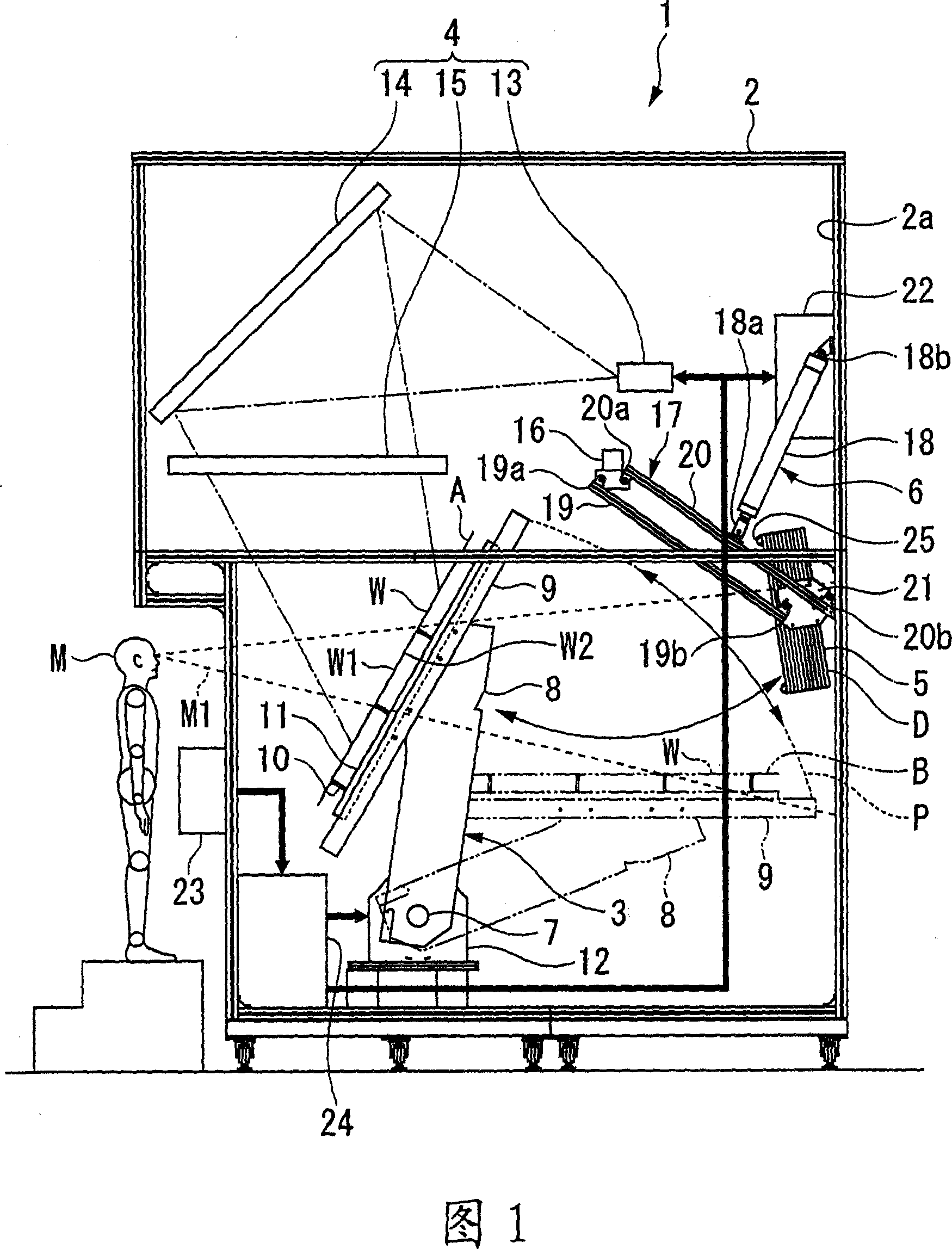
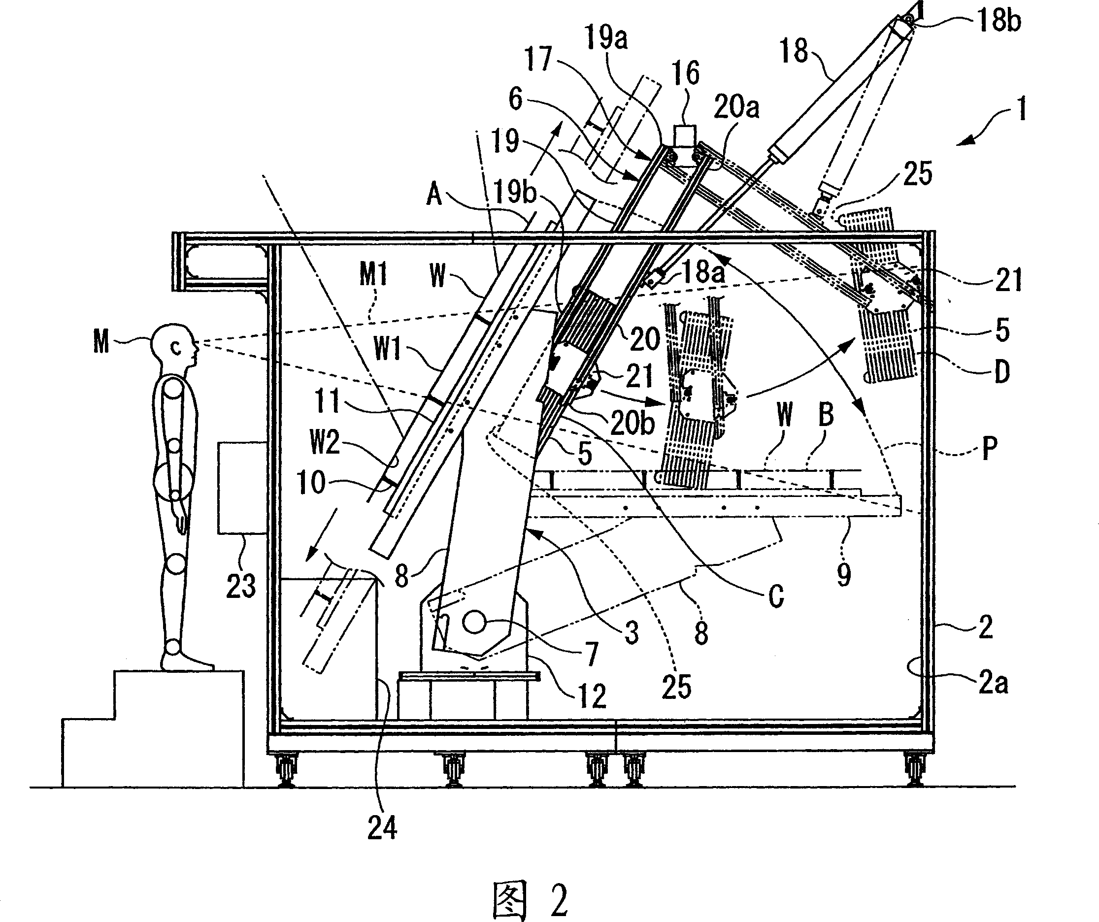
[0040] 1 and 2 show a first embodiment of the present invention. FIG. 1 shows an overall view of a substrate inspection device, and FIG. 2 shows an enlarged side view.

[0041] As shown in FIG. 1 , the substrate inspection apparatus 1 has: a housing 2 that forms an outer contour; a holder rotating mechanism 3 that rotates a substrate holder 11 holding a substrate W to be inspected; an epi-illumination unit 4 that illuminates the substrate W to be inspected. The surface W1 on which the pattern is formed is epi-illuminated; the backlight 5 illuminates the back surface W2 opposite to the surface W1 of the substrate W to be inspected; and the moving unit 6 of the backlight 5 . The inner wall surface 2a of the housing 2 is black so that light will not be diffusely reflected. In addition, the stand rotation mechanism 3 has: a turn shaft 7 provided at the turn center; a pair of turn arms 8 rotatably supported on the turn shaft 7 at base end portions of the arms; a pair of stand guid...

no. 2 Embodiment approach

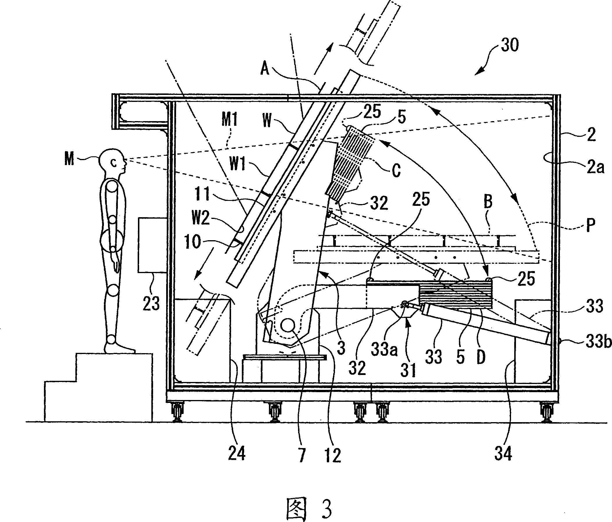
[0052] Fig. 3 shows a second embodiment of the present invention, and shows an enlarged side view of a substrate inspection device. In this embodiment, the same reference numerals are assigned to the same components as those used in the above-mentioned embodiment, and description thereof will be omitted.

[0053] As shown in FIG. 3 , in the substrate inspection apparatus 30 of this embodiment, the moving unit 31 that moves the backlight 5 is composed of a rotating arm 32 that is rotatably supported at the base end by a pair of rotating arms 8 . On the shaft that is coaxial with the rotating shaft 7; the actuator 33 rotates the rotating arm 32. The backlight 5 is fixed to the tip of the swivel arm 32 , and the backlight 5 is rotatable from a retracted position D below the substrate delivery position B of the holder guide 9 to an irradiation position C. As shown in FIG. In addition, one end 33a of the actuator 33 is connected to the rotating arm 32 with a pin, and the other end...

no. 3 Embodiment approach

[0056] Fig. 4 shows a third embodiment of the present invention, and shows an enlarged side view of a substrate inspection device. In this embodiment, the same reference numerals are assigned to the same components as those used in the above-mentioned embodiment, and description thereof will be omitted.

[0057] As shown in FIG. 4 , in the substrate inspection apparatus 40 of this embodiment, the moving unit 41 that moves the backlight 5 is composed of a rotating arm 42 that is rotatably supported at the base end of the frame rotating mechanism 3 . Above the swivel area P; the electric motor 43 which turns the swivel arm 42 . The backlight 5 is fixed to the front end portion of the rotating arm 42 and is set so as to be parallel to the substrate W to be inspected when located at the irradiation position C. As shown in FIG. In addition, the turning arm 42 can move the backlight 5 out of the turning area P of the stand turning mechanism 3 , and move to the retracted position D ...


PUM


Abstract

An apparatus for inspecting a substrate 1 is provided with a holder rotating mechanism 3 for holding and rotating a test substrate W, a back light 5 which irradiates light onto a back side surface W2 that is opposed to a front side surface W1 of the test substrate W, and moving means 6 for moving the back light 5. A rotating arm 17, which constitutes the moving means 6, includes two link levers 19 and 20 and a stationary plate 21 which is a stationary member. The two link levers 19 and 20 are rotatably supported on a supporting member 16 at one ends (19a, 20a) thereof, respectively, the one ends being separated from one another by a predetermined distance. Further, the link levers 19 and 20 are rotatably supported on the stationary plate 21 at the other ends (19b, 20b) thereof, respectively, the other ends being separated from one another by a predefined distance. The back light 5 is fixedly secured to the stationary plate 12.

Description

technical field [0001] The present invention relates to a substrate inspection device capable of visually inspecting a glass substrate or the like by means of a transmissive backlight. Background technique [0002] Conventionally, in the manufacturing process of flat panel displays (FPDs), etc., as a method of visually inspecting glass substrates, etc., a method of observing with epi-illumination from the front side of the substrate to be inspected, and at the same time, using light from the back surface Observation is carried out with transmitted illumination from the side, and further, defects such as damage are detected in detail. For example, there has been proposed a substrate inspection device that includes: a swing table that supports a substrate to be inspected so that it can swing; a reflective lighting unit that irradiates the surface of the substrate on the swing table; Transmission is performed on a substrate on a swing table (for example, refer to Patent Docume...

Claims


Application Information

Patent Timeline
IPC IPC(8): G01N21/958G01N21/896
CPCG01N21/88G01N21/8806G01N21/958G01N2021/9513G02F1/1309
Inventor 木内智一
Owner OLYMPUS CORP
Learn More