
Conveying device and conveying method of electronic component

A technology of electronic components and handling devices, which is applied in the direction of measuring devices, optical devices, instruments, etc., can solve the problems of complicated equipment costs, inability to ensure reliability, etc., and achieve the effect of efficient appearance inspection

Active Publication Date: 2014-04-16
MURATA MFG CO LTD
View PDF6 Cites 2 Cited by
  • Summary
  • Abstract
  • Description
  • Claims
  • Application Information

AI Technical Summary

Problems solved by technology

[0004] However, in order to constitute the cited document 1 figure 2 , image 3 The inspection device shown requires a stage as a fixed unit of the inspection device, an X stage and a Y stage for positioning a pallet held across the stage, and an X-axis dedicated to the X stage and the Y stage. Motor and X screw shaft, Y axis motor and Y screw shaft, etc., which lead to problems such as complexity of equipment and increase in equipment cost
[0005] Therefore, in order to suppress the equipment cost, it may be considered to simplify the equipment by manually moving the pallet, but in this case, for example, when components arranged on most columns are checked sequentially by column, there is a possibility of skipping a column and moving the pallet, Thus, there is a problem that sufficient reliability cannot be ensured, that is, whether all components are checked

Method used


Image

  • Conveying device and conveying method of electronic component
  • Conveying device and conveying method of electronic component
  • Conveying device and conveying method of electronic component

Examples


Embodiment Construction

[0043] Embodiments of the present invention are shown below, and features of the present invention will be described in more detail.

[0044] In this embodiment, the case where an external appearance inspection is performed on a module component that is an electronic component, in which a semiconductor chip, a capacitor chip, etc. is mounted on or inside a ceramic substrate or a resin substrate, will be described Electronic components for surface mount components.

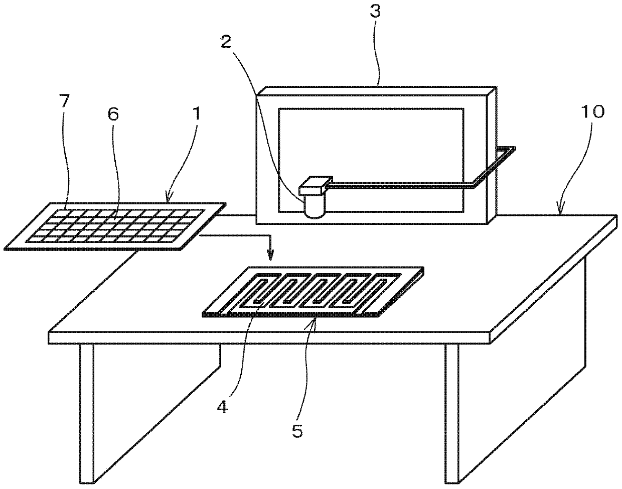
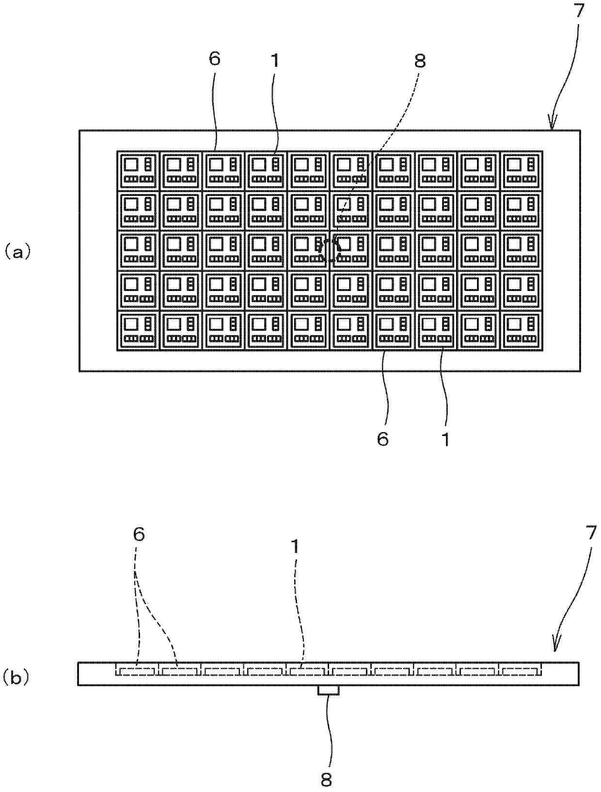
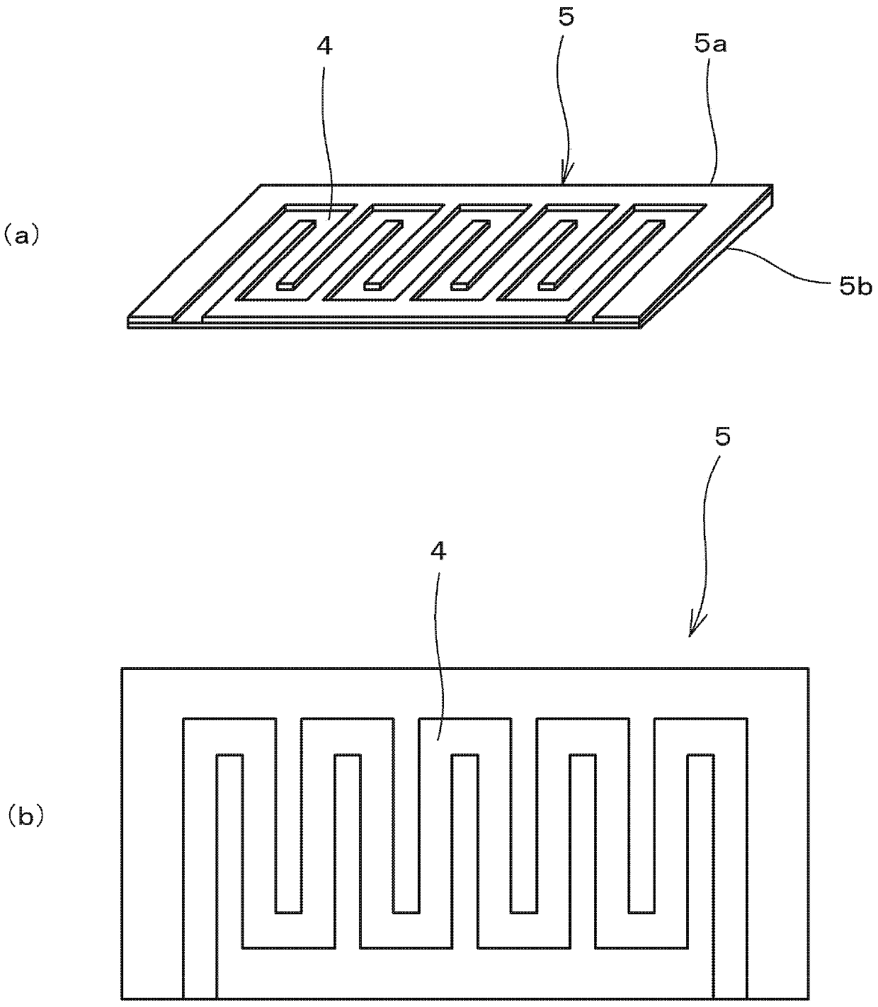
[0045] figure 1 It is a perspective view which shows the conveyance apparatus of the electronic component concerning embodiment of this invention, figure 2 It is a diagram showing a tray having a plurality of storage sections for storing electronic components (module components) to be subjected to visual inspection, (a) is a plan view showing a state in which module components are stored in the storage sections, (b) is the main view, image 3 It is a figure which shows the jig for guidance which comprises the c...


PUM


Abstract

The present invention provides a conveying device and a conveying method of an electronic component, by which the appearances of the electronic components accommodated in a plurality accommodating parts of a tray can be detected reliably without a complicated device. A path formed at the lower surface side of the tray 7 is configured in a way that a protrusion part (8) is meshed with a continuous guiding groove (4) possessed by a guiding clamp (5) which is arranged at a fixed position relative to a fixed camera (2). The mobile tray (7) defines the path in a way that the protrusion part (8)is moved along the guiding groove (4), so that the electronic components accommodated in the plurality of accommodating parts (6) are provided in a shooting area of the fixed camera orderly, and the appearances of the module components are detected by observing the images of the module components (1) shot by the fixed camera (2). In addition, the plurality of module components exists in the shooting area of the fixed camera, the images of the module components are displayed, so that the appearances of the module components are detected.

Description

technical field [0001] The present invention relates to a conveying device and method for electronic components, and more specifically, to a device and method for sequentially conveying electronic components respectively stored in a plurality of storage portions of a tray. Background technique [0002] In recent years, various electronic devices are widely used in mobile communication terminals and the like. For electronic components such as module components, shielding cases, and coaxial cables mounted in such electronic equipment, in order to prevent defects and failures of electronic equipment, it is necessary to perform inspections and eliminate defective products in advance. In addition, there is an appearance inspection for these electronic components to check whether the appearance is good. [0003] As an appearance inspection method for electronic components, for example, Patent Document 1 discloses a pallet component inspection method in which a camera is used to r...

Claims


Application Information

Patent Timeline
IPC IPC(8): G01N21/84G01B11/00
Inventor 石井俊宏
Owner MURATA MFG CO LTD
Learn More