Seal

A stamp and seal technology, applied in the field of stamps, can solve the problems of uneven stamp surface, uneven stamp image, unrecognized date, etc., and achieve a good effect of stamping

Inactive Publication Date: 2007-04-04
BROTHER KOGYO KK
View PDF1 Cites 3 Cited by
  • Summary
  • Abstract
  • Description
  • Claims
  • Application Information

AI Technical Summary

Problems solved by technology

[0002] Conventional stamps, which can form a single stamp image by combining two or more stamp faces, have such a problem that if the heights of the corresponding stamp faces are shifted, the corresponding stamp faces are not flush with each other, so , local unevenness may occur within the stamp image when the stamp is knocked in such a state
Unless properly adjusted in the case of date stamps, such problems can occur, for example, that the date may not be recognized from the image of the stamp

Method used


Image

  • Seal
  • Seal
  • Seal

Examples


Embodiment Construction

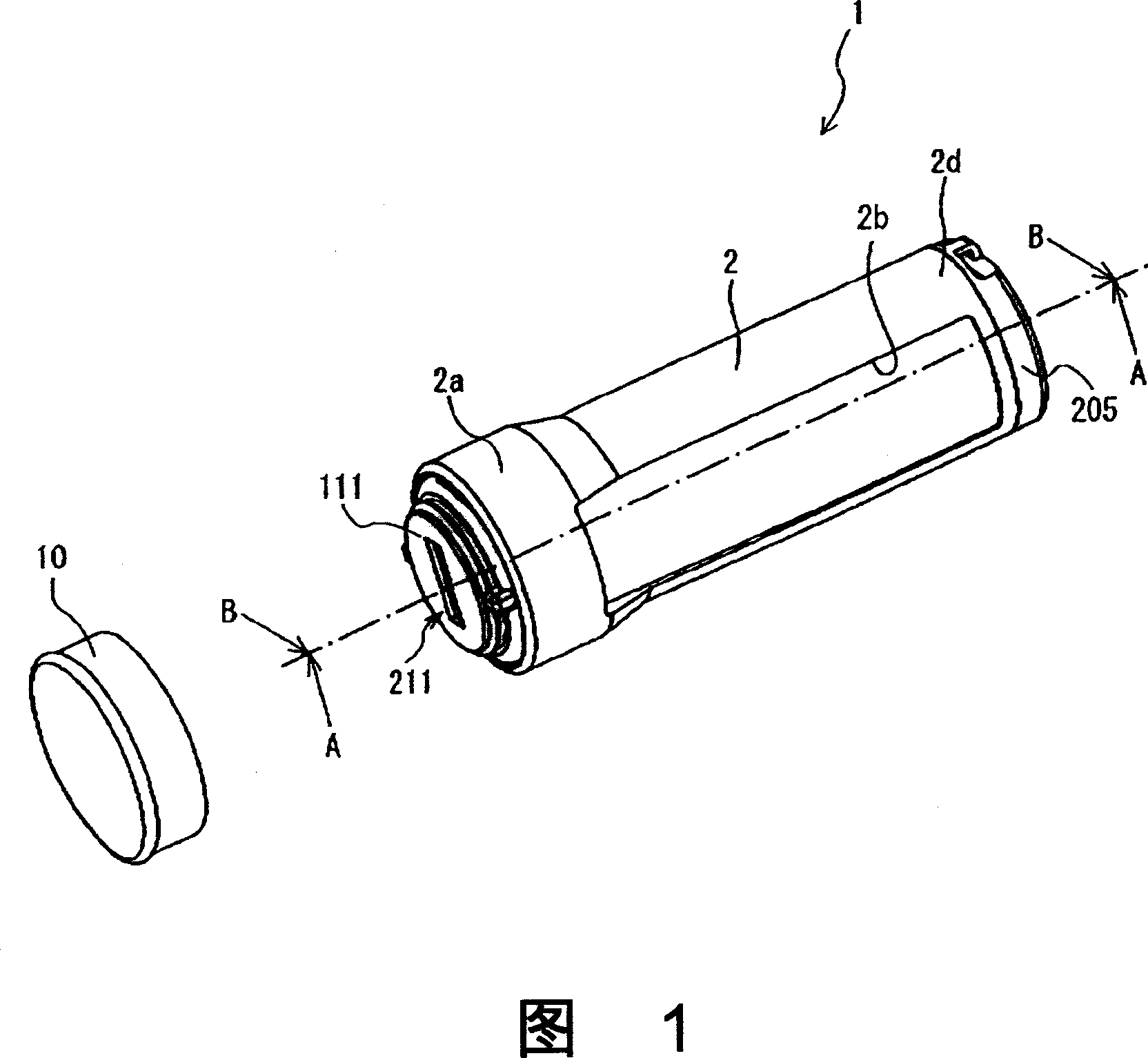
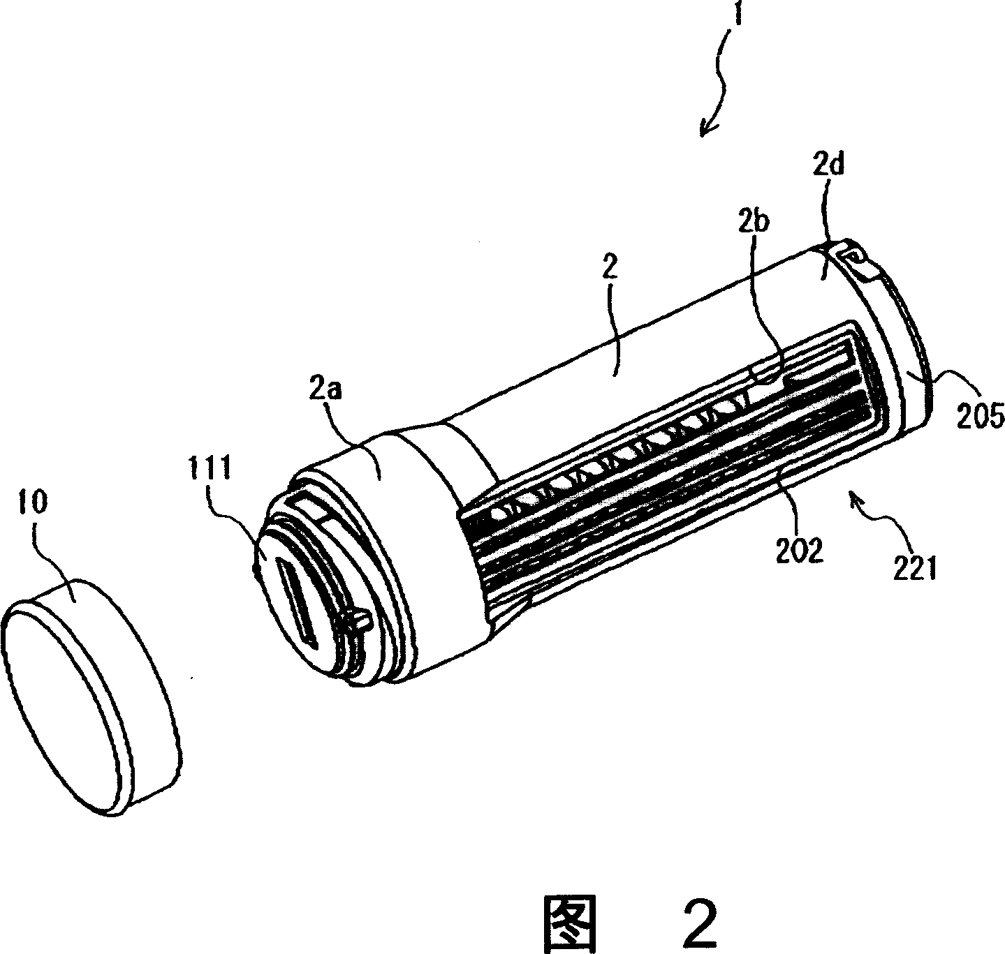
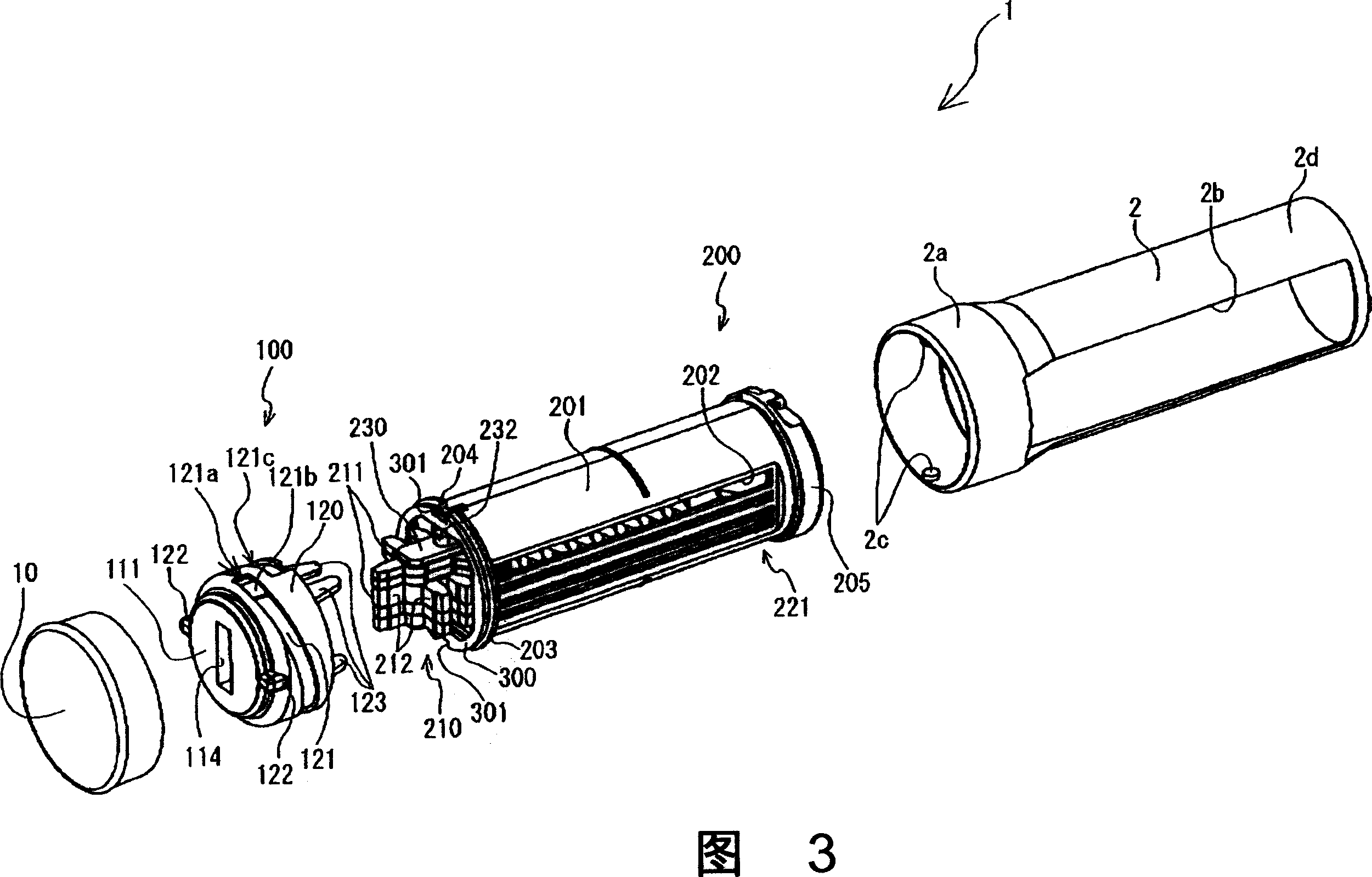
[0043] Next, an embodiment of the stamp of the present invention will be described with respect to a date stamp 1 . First, a first embodiment will be described with reference to FIGS. 1-6. FIG. 1 is a perspective view of a date stamp 1 in a state where stamping is permitted. Fig. 2 is a perspective view of the date stamp 1 in a state allowing its stamp face 211 to be changed. FIG. 3 is a disassembled perspective view of the date stamp 1 . FIG. 4 is a perspective view of a holding body 230 holding a movable stamp member 210 . FIG. 5 is a sectional view of the date stamp 1 viewed from the direction of arrow A with respect to the dotted line in FIG. 1 . Fig. 6 is a sectional view of the date stamp 1 when stamping.

[0044] As shown in FIGS. 1 and 2, the date stamp 1 has a substantially cylindrical main body case 2, and a cylindrical end portion 2a on one end of the main body case 2 has a hole made slightly larger than the body thereof. The cylindrical end portion 2a has a st...


PUM


Abstract

In a fixed stamp part (100), a cylindrical holding member (125) keeps a fixed stamp member (112) and an ink storage body (113) at the side away from the ink storage body (113), and A frame member (120) with an L-shaped section is set at the side away from the fixed stamp member (112), so that it can be fitted to the outer periphery of the holding member (125), thereby maintaining a stamp face ( 111) and exposed. A portion of the fixed stamp member (112) near the outer periphery is pinched between the frame member (120) and the retaining member (125) in a compressed state as the frame member (120) is fitted to the retaining member (125 ), and an exposed portion of the fixed stamp member (112) has a height difference (H) between the end face of the frame member (120) and the stamp face (111). A damper member (300) is provided between the frame member (120) and a flange (203) provided on the support case (201) of the movable stamp part (200).

Description

technical field [0001] The present invention relates to a stamp capable of forming a stamp image by combining two stamp faces. Background technique [0002] Conventional stamps, which can form a single stamp image by combining two or more stamp faces, have such a problem that if the heights of the corresponding stamp faces are shifted, the corresponding stamp faces are not flush with each other, so , local unevenness may occur within the stamp image when the stamp is struck in such a state. Unless the adjustment is properly made in the case of a date stamp, such a problem occurs that, for example, the date may not be recognized from the image of the stamp. In such a date stamp, a single stamp image is formed by combining a stamp face selected from a rotating stamp body having a plurality of stamp faces (date parts) and a stamp face (company name, etc.) of a fixed stamp body . [0003] For example, according to Patent Document 1, by turning an adjustment ring for moving th...

Claims


Application Information

Patent Timeline
Patent Type & Authority Applications(China)
IPC IPC(8): B41K1/10B41K1/50
Inventor 小林慎治北村裕美神户一幸
Owner BROTHER KOGYO KK
Why Eureka
Try Eureka