Multifunctional feed feeder

A feeder, multi-functional technology, applied in the application, beekeeping, animal husbandry and other directions, can solve the problems of affecting the success rate of queen bee mating, backward feeding methods, labor and time-consuming, etc., to save feed, easy to maintain strong Group, not easy to hurt the effect of heat

Inactive Publication Date: 2007-04-11
陈盛禄
View PDF0 Cites 5 Cited by
  • Summary
  • Abstract
  • Description
  • Claims
  • Application Information

AI Technical Summary

Problems solved by technology

The second is that the feeding method is backward. In the past century, most of them have used aluminum pots to pack honey out of the box for feeding. Easy to affect the success rate of queen bee mating

Method used


Image

  • Multifunctional feed feeder
  • Multifunctional feed feeder
  • Multifunctional feed feeder

Examples


Embodiment 1

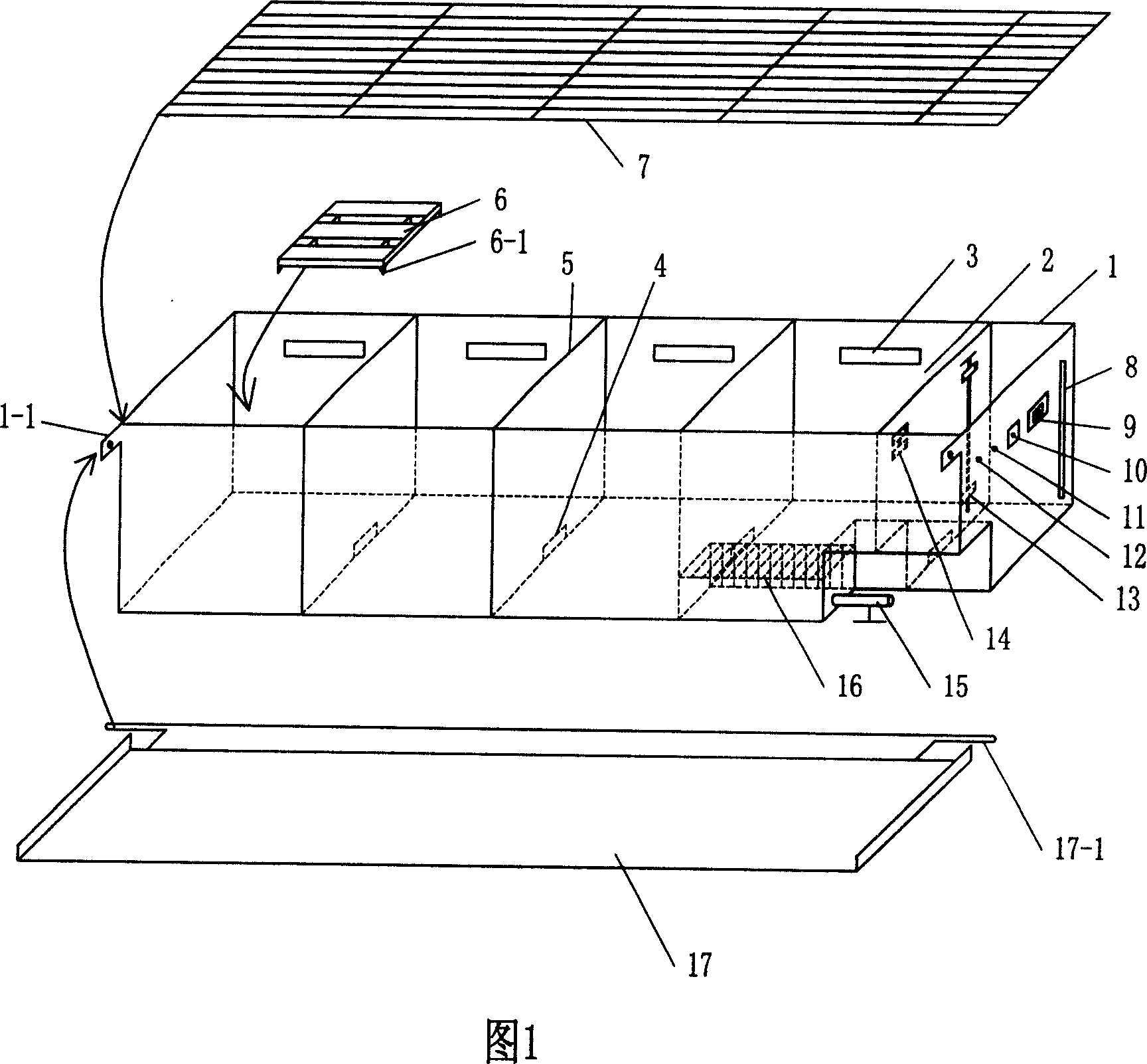
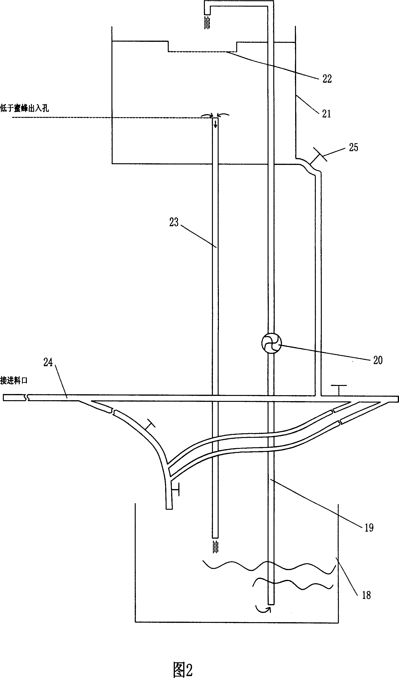
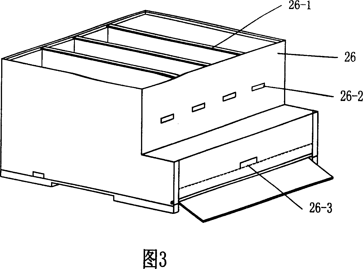
[0021] Embodiment 1: with reference to accompanying drawing: this multifunctional feeder comprises the groove 1 that constitutes main body, is separated into four storage chambers 2 for depositing bee feed (honey or syrup) by dividing plate 5 in the groove 1, Corresponds to the four-chambered mating box. The bottom of the dividing plate 5 is provided with a diversion hole 4 that connects the storage chambers 2 on both sides. The height of the diversion hole 4 is about 3 millimeters, which is less than the height of the bees, so that the bees cannot pass through, and the bees in each chamber are prevented from mixing with each other. Whereas the syrup can flow naturally. The side wall of each storage chamber 2 has a bee access hole 3, which corresponds to the four bee crawling holes 26-2 on the front wall of the beehive 26. The bottom of the tank 1 is provided with a feed port 15 communicating with the storage chamber 2, and the feed port 15 is provided with a grid cover 16 to...


PUM


Abstract

A multifunctional feed carrier comprises a trough acting as its main body, chambers for storing fodder of bees formed in the trough, holes for bees passing in and out located on the sidewalls of the chambers and corresponded to the opens of the beehive, ventilation grid for obstructing bees from entering the trough covering the same. The advantages are laborsaving, timesaving, and feedstuff saving, improving the honey yield and bee livability regardless of the seasons.

Description

technical field [0001] The invention relates to a bee feeding device, in particular to a multifunctional feeder for feeding bees. Background technique [0002] In the management of the bee colony's annual life, taking honey and feeding honey (or syrup) are the two most important tasks, wherein feeding honey is more important and more frequent than taking honey; the workload is also greater. There are two main reasons, one is winter and summer; strong wind and rain; lack of nectar or no flow of nectar, resulting in insufficient feed than when it is desirable not to feed honey. The second is that the feeding method is backward. In the past century, most of them have used aluminum pots to pack honey out of the box for feeding. It is easy to affect the success rate of queen bee mating. So invent brand-new, labor-saving and trouble-saving multi-purpose four-chamber feeder close to the beehive outer wall is very necessary and urgent. Contents of the invention [0003] The pre...

Claims


Application Information

Patent Timeline
Patent Type & Authority Applications(China)
IPC IPC(8): A01K53/00
Inventor 陈盛禄苏松坤
Owner 陈盛禄
Why Eureka
Try Eureka