Sealed water saving toilet

A sealed toilet technology, applied in water supply devices, flushing equipment with water tanks, buildings, etc., can solve the problems of wasting water and flushing tiny dirt down

Inactive Publication Date: 2007-04-11
段鳗珊
View PDF0 Cites 0 Cited by
  • Summary
  • Abstract
  • Description
  • Claims
  • Application Information

AI Technical Summary

Problems solved by technology

[0003] The disadvantage of this U-shaped sinking water bend is: the water flow of flushing the toilet has changed the direction of flow several times, and the pressure of flushing the dirt down has become very small, so it can only be mixed with the sundries by a large water flow. Float through the U-shaped sinkhole to achieve the purpose of sanitary ware
[0004] The U-shaped sinking water bend wastes water like this, and the significance of saving water is very important

Method used


Image

  • Sealed water saving toilet

Examples


Embodiment Construction

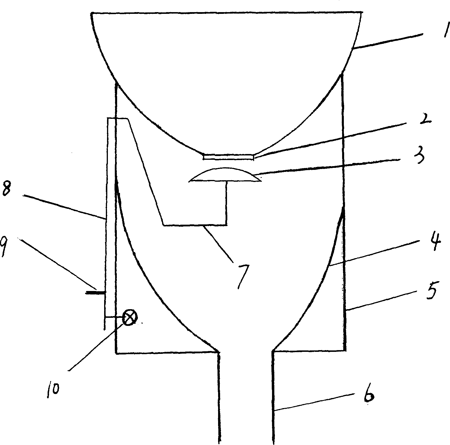
[0008] Sealing ring 2 and sealing plug 3 are installed at the bottom of the bedpan as shown in the figure, and sealing ring 2 may not be used as long as sealing plug 3 can be sealed with the bedpan main body outlet. The lower end of the sealing plug is connected with the transmission mechanism for controlling opening and closing. The transmission mechanism links to each other with the running water valve again, and when the sealing plug was opened, the running water was also opened simultaneously, and the running water was also closed simultaneously when closing. The bedpan main body 1 is supported by the bedpan base 5, and a base liner 4 similar to the bedpan 1 is designed in the bedpan base 5, and then the bottom of the base liner 4 is connected with the sewer pipe 6. I have only drawn a kind of foot-operated transmission mechanism device in the design scheme, and multiple devices such as electric, manual, hydraulic pressure can also be installed on the sealing plug 3 in add...


PUM


Abstract

The water saving sealed toilet has one sealing stopper to replace U-trap. The sealing stopper installed in the outlet of the toilet has driving mechanism interlocked with the water valve. Replacing the sealing stopper for the U-trap can reduce the toilet flushing resistance greatly and reach the aim of saving water.

Description

technical field [0001] The invention relates to a closet, in particular to a water-saving closet which uses a sealing device to replace the old-style closet and must use a sink. Background technique [0002] As we all know, among the necessary toilets for every household in the city, a U-shaped sinkhole must be installed between the toilet and the sewer. The main function of this submerged water bend is to ensure that the odor of the sewer pipe is completely isolated from the top of the toilet. From ancient times to the present, people have used U-shaped sinking water bends to block odors, and there is no other choice. [0003] The disadvantage of this U-shaped sinking water bend is: the water flow of flushing the toilet has changed the direction of flow several times, and the pressure of flushing the dirt down has become very small, so it can only be mixed with the sundries by a large water flow. Float through the U-shaped sinking water bend to achieve the purpose of sani...

Claims


Application Information

Patent Timeline
Patent Type & Authority Applications(China)
IPC IPC(8): E03D5/012
Inventor 段鳗珊
Owner 段鳗珊
Why Eureka
Try Eureka