Torque restrictor

A technology of torque limiter and outer ring, used in couplings, slip couplings, mechanical equipment, etc., can solve the problem of insufficient rigidity of the arc part, and achieve the purpose of suppressing vibration, suppressing noise, and improving rigidity. Effect

Inactive Publication Date: 2007-04-11
NTN CORP
View PDF3 Cites 6 Cited by
  • Summary
  • Abstract
  • Description
  • Claims
  • Application Information

AI Technical Summary

Problems solved by technology

[0012] On the other hand, although the improved torque limiter of said patent application can basically achieve the intended purpose, because the front end faces 57', 58, and 58' simply pushes against the side surface of the protrusion of the outer ring member (not shown) and the protrusion of the cover member 54, so the rigidity of the arc parts 57 and 58 is insufficient.

Method used


Image

  • Torque restrictor
  • Torque restrictor
  • Torque restrictor

Examples


Embodiment Construction

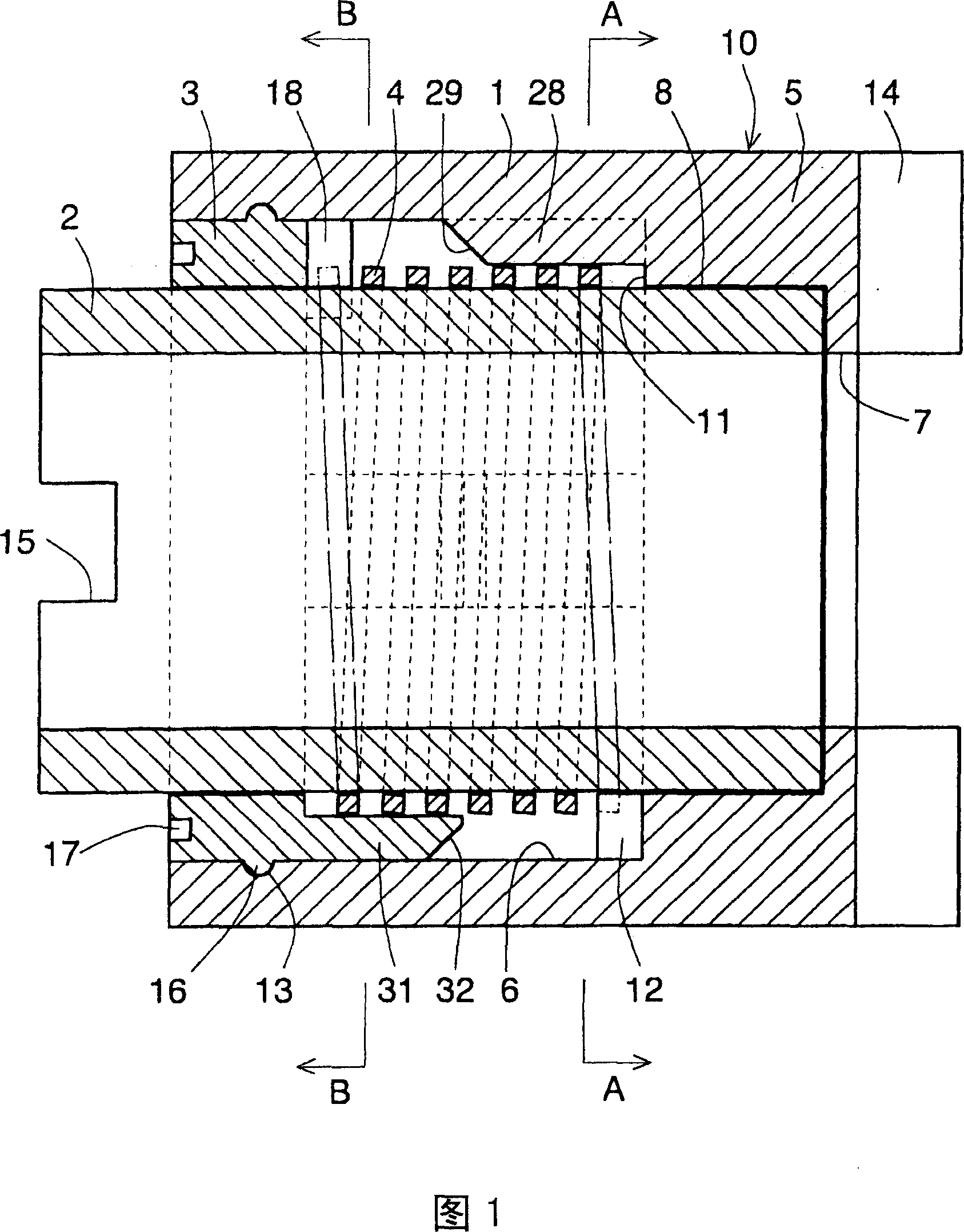
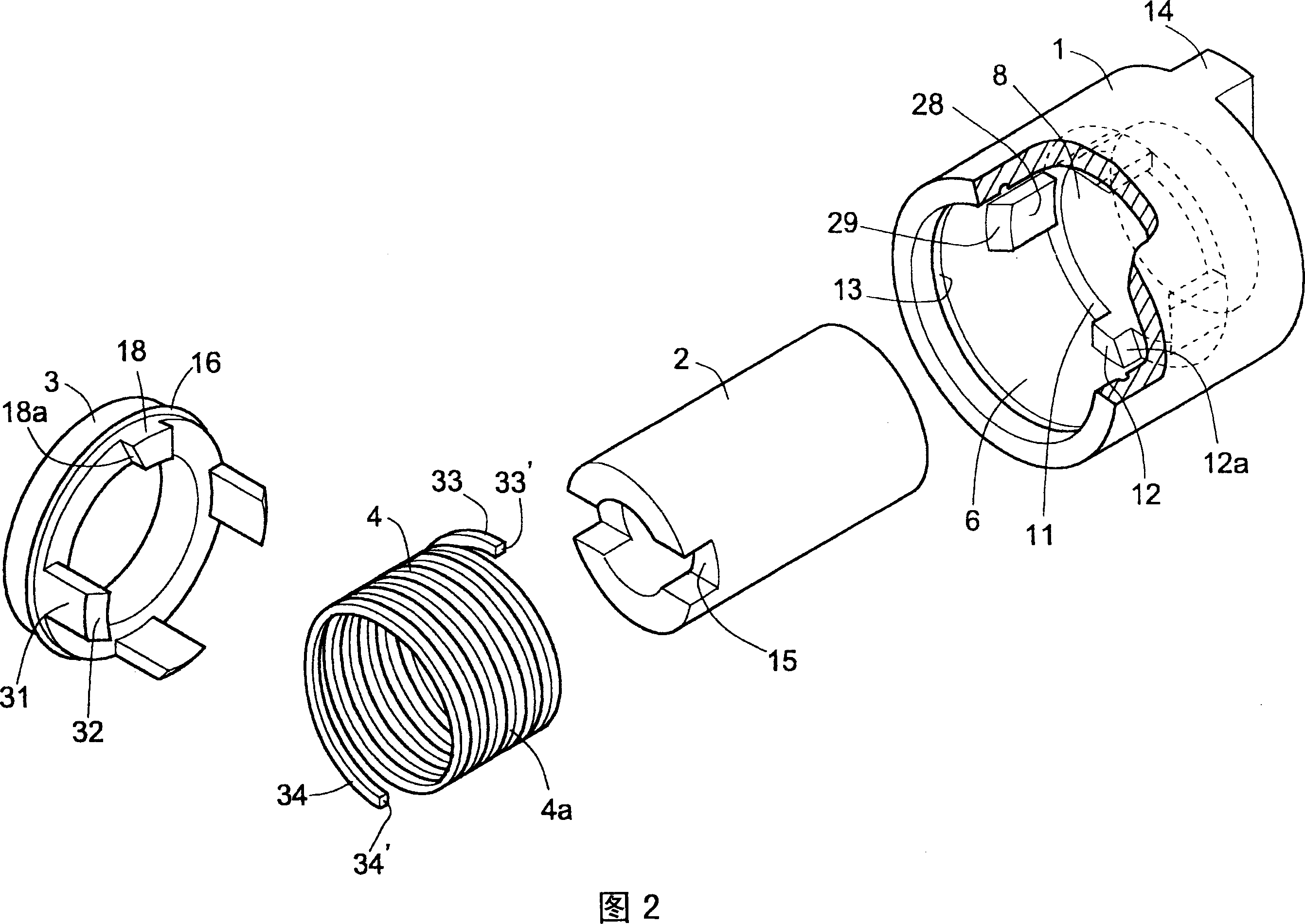
[0029] Hereinafter, the embodiments of the present invention will be described with reference to the drawings. As shown in FIGS. 1 to 3, the torque limiter 10 of the present embodiment is composed of an outer ring member 1, an inner ring 2, an annular cover member 3, and a coil spring 4 as in the conventional case. A sleeve portion 5 is provided on one end of the outer ring member 1, and an inner diameter surface 6 having a larger diameter than the coil spring 4 is formed between the sleeve portion 5 and the open end of the other end. A shaft insertion hole 7 is provided in the center of the sleeve portion 5, and an inner ring support portion 8 having a larger diameter than the shaft insertion hole 7 is provided inside the shaft insertion hole 7.

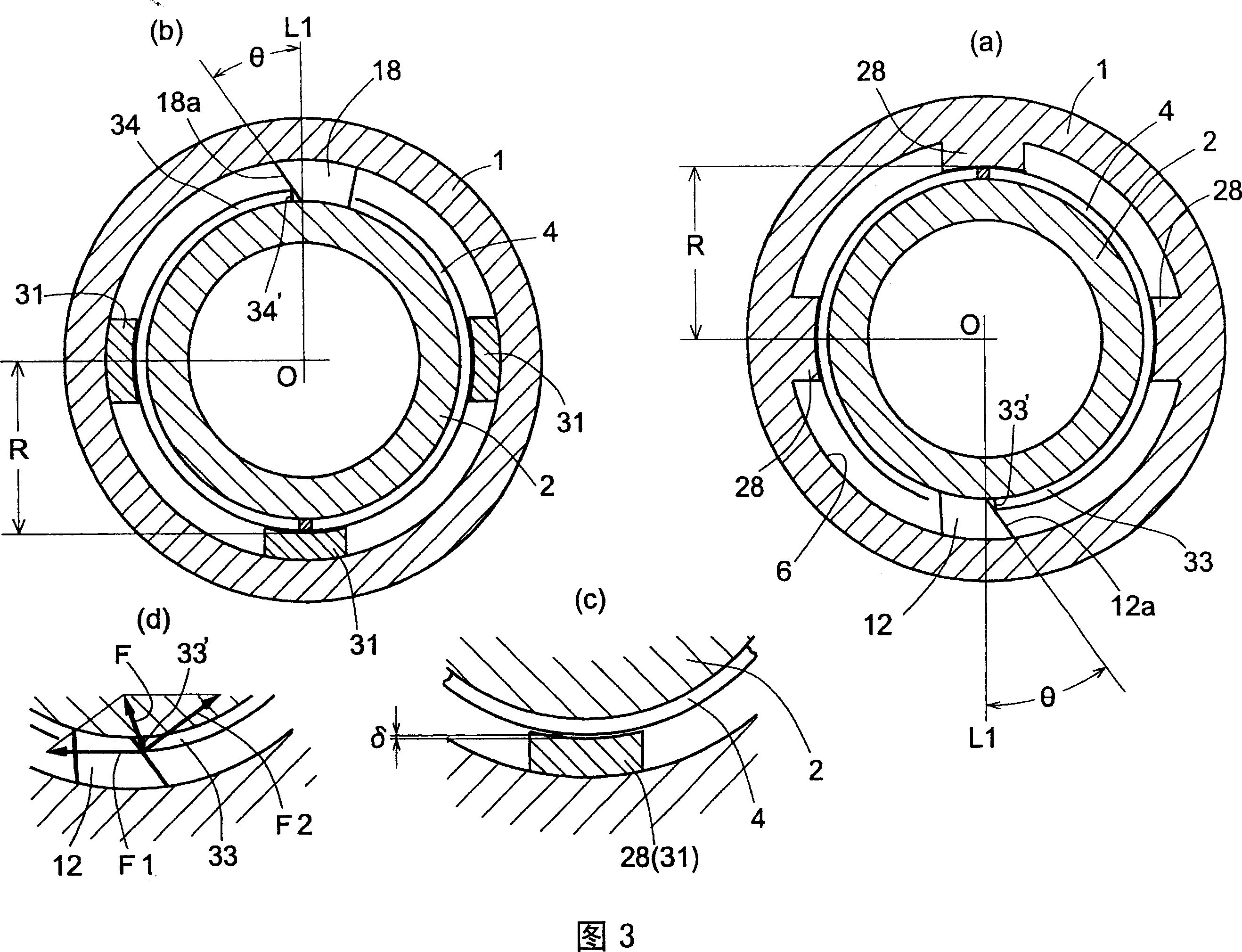
[0030] A part of the inner end surface 11 of the sleeve portion that forms the stepped portion of the inner ring support portion 8 and the inner diameter surface 6 is provided with an outer ring member projecting portion 12 (see FIG. 3(a)...


PUM


Abstract

The present invention provides a spring-type torque limiter, which prevents vibration and abnormal sound during use by increasing the rigidity of both ends of a coil spring. By making the side faces of the outer ring member protrusion (12) and the cover member protrusion (18) on both ends of the coil spring (4) mounted on the outer diameter surface of the inner ring (2) have an inclination angle , the movement of the two ends in the direction of the outer diameter is restricted, thereby increasing the rigidity, and suppressing the generation of vibration and abnormal sound of the coil spring (4).

Description

Technical field [0001] The present invention relates to a spring-type torque limiter used in office equipment such as printers and copiers, and particularly relates to preventive measures to prevent the vibration of coil springs or the generation of abnormal sounds. Background technique [0002] As a conventionally known spring-type torque limiter used in office equipment and the like, as shown in FIG. 5, it is composed of the following components, namely: an outer ring member 41; an inner ring 43, which is inserted into the outer ring member 41, And is rotatably supported on the sleeve portion 42 at one end of the outer ring member 41; the coil spring 44 is installed on the outer diameter surface of the inner ring 43 with the required interference; and the cover member 49, which is fitted and fixed on the inner diameter surface at the other end of the outer ring member 41, closes the inner diameter surface and the outer diameter surface of the inner ring 43, and rotatably suppor...

Claims


Application Information

Patent Timeline
Patent Type & Authority Applications(China)
IPC IPC(8): F16D7/00
Inventor 本多正明
Owner NTN CORP
Why Eureka
Try Eureka