Filtration membrane cleaning method and apparatus using this method

A filter membrane and equipment technology, applied in the field of filter membrane cleaning, can solve problems such as the need to improve efficacy

Inactive Publication Date: 2007-04-11
DEGREMONT SOC DITE
View PDF1 Cites 9 Cited by
  • Summary
  • Abstract
  • Description
  • Claims
  • Application Information

AI Technical Summary

Problems solved by technology

However, its efficacy needs to be improved and maintained over time

Method used


Image

  • Filtration membrane cleaning method and apparatus using this method
  • Filtration membrane cleaning method and apparatus using this method
  • Filtration membrane cleaning method and apparatus using this method

Examples


Embodiment Construction

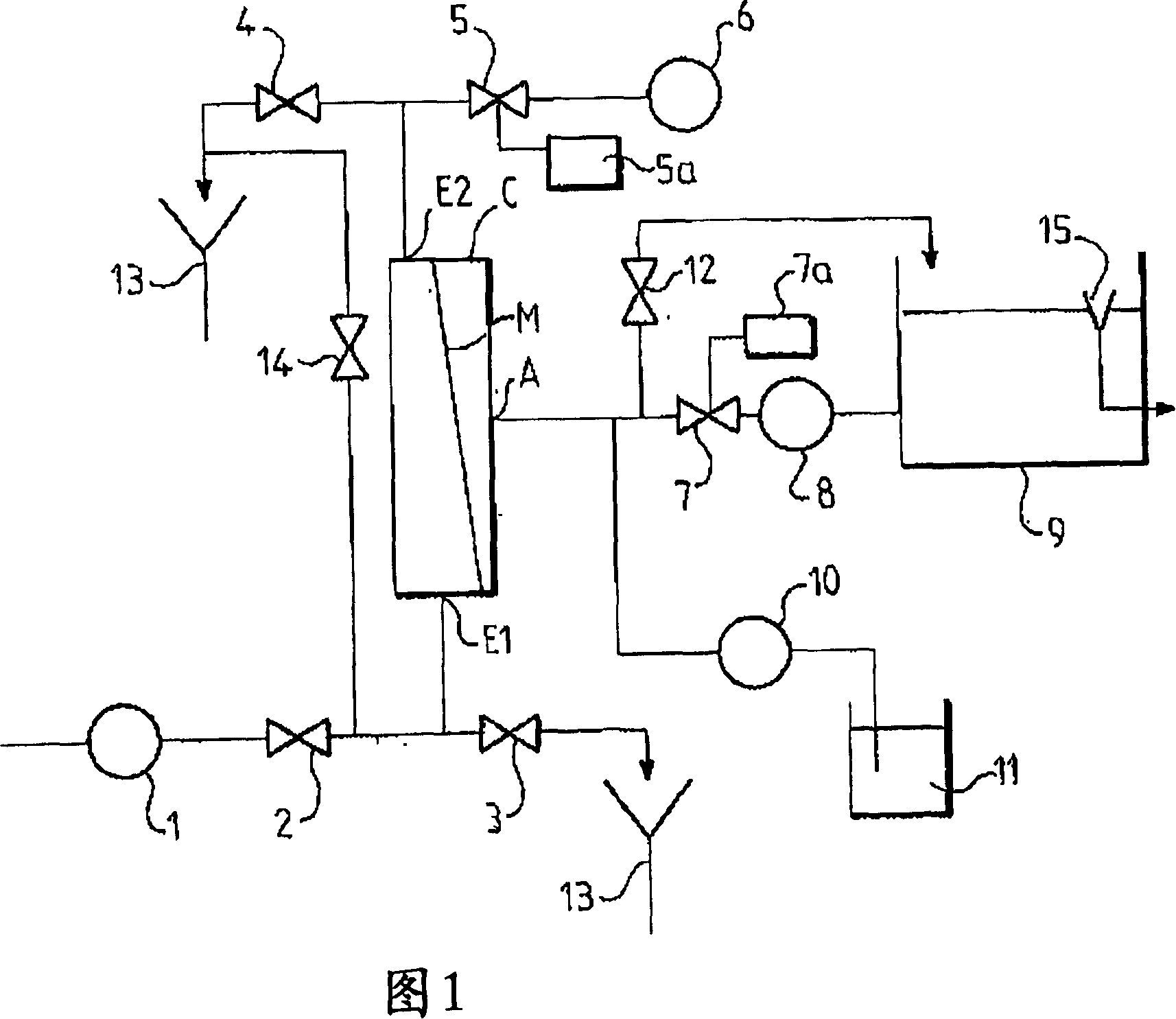
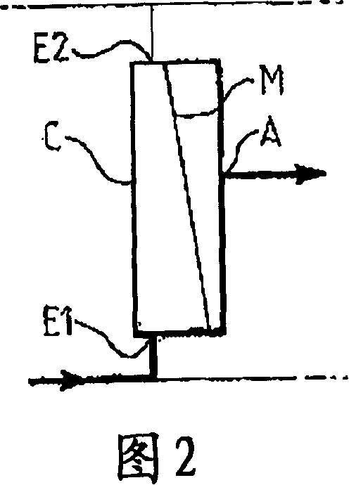
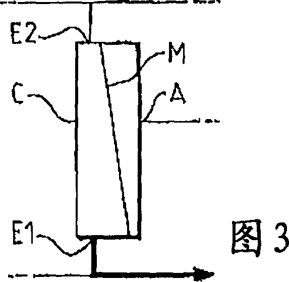
[0033] [33] The drawings, in particular FIG. 1 , show a device for deposit removal of filter membranes, ultrafiltration membranes, microfiltration membranes, ultrafiltration membranes or ultrafiltration membranes using the method according to the invention. The membrane module M shown in Fig. 1 has a tubular geometry and is used in a case C where a group of inner skin hollow fibers is arranged centrally. The box C is equipped with two holes E1, E2, which are respectively the lower hole and the upper hole, which can be used as outlet and / or inlet. The holes E1 , E2 are connected to a centralized compartment formed by the inner space of the hollow fibers. Inside the box, the space around and between the membranes forms the permeable compartment with a mid-position relative to the height of the module Exit A. In other embodiments, the outlet A may be axial relative to the diameter of the assembly.

[0034] [34] The membrane M is used for the filtration of liquids, usually wate...


PUM


Abstract

The invention relates to a method of cleaning membrane filters comprising hollow fibres and an inner skin. The inventive method comprises the following steps consisting in: emptying the concentrate compartment in order to release the liquid to be filtered contained therein and the suspended matter, and, subsequently, performing a backwashing step involving the passage of liquid from the permeate compartment into the concentrate compartment through membranes in order to detach and release impurities deposited thereon, while circulating a gas in the concentrate. According to the invention, backwashing liquid and / or gas pulses are produced by control means (5, 5a; 7, 7a) during at least one backwashing phase.

Description

technical field [0001] [01] The present invention relates to a method for cleaning filter membranes made of peauinterne hollow fibers, installed in a housing, and with which are defined accumulations in suspension and on said membranes. A centralized compartment for residual material, and a permeable compartment for collecting filtrate. Background technique [0002] [02] Filtration of liquids, especially water, produces a particulate composite mass and a dissolved fraction retained by the membrane. This filter cake will initially be fouling of the membrane, manifested as an increase in transmembrane pressure at constant permeate flow, or as a decrease in permeate flow at constant transmembrane pressure. [0003] [03] Silt reduction methods are used to remove the filter cake. With permeable introduction in the opposite direction to the filtration direction applied in production, reverse osmosis is generally formed, whereby the filter cake is driven by the single-phase flow ...

Claims


Application Information

Patent Timeline
Patent Type & Authority Applications(China)
IPC IPC(8): B01D65/02B01D63/02
CPCB01D2321/168B01D65/02B01D2321/185B01D2321/164B01D63/02B01D2321/04B01D2321/162B01D2321/2066B01D65/00
Inventor V·博纳利M·彼得里F·科拉
Owner DEGREMONT SOC DITE
Why Eureka
Try Eureka