
Vibration device

The technology of a vibrating device and a driving device, which is applied in the direction of vibrating fluid, can solve the problems of difficult vibration removal, low vibration frequency, poor effect, etc., and achieves the effects of convenient use, improved vibration efficiency, and reduced labor intensity

Inactive Publication Date: 2007-04-18
SHENZHEN FUTAIHONG PRECISION IND CO LTD
View PDF0 Cites 5 Cited by
  • Summary
  • Abstract
  • Description
  • Claims
  • Application Information

AI Technical Summary

Problems solved by technology

[0003] However, the above-mentioned vibration removal process is done manually, the labor intensity is high, the vibration frequency is low, and the effect is not good, and some containers containing ink or paint are relatively large in volume and quality, and it is difficult to complete the vibration removal process by manpower.

Method used


Image

  • Vibration device
  • Vibration device
  • Vibration device

Examples


Embodiment Construction

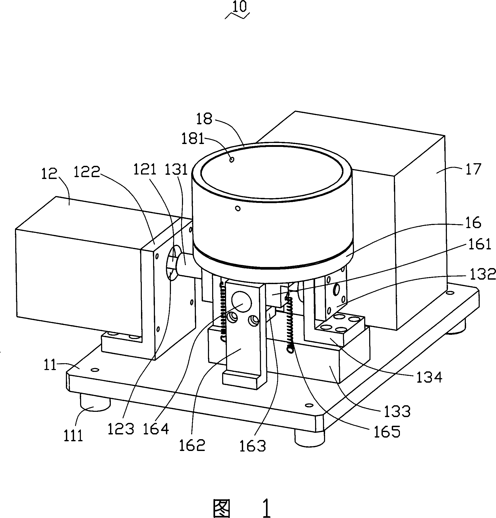
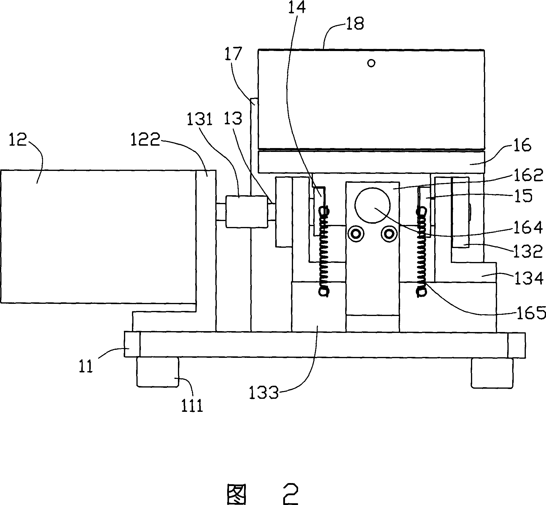
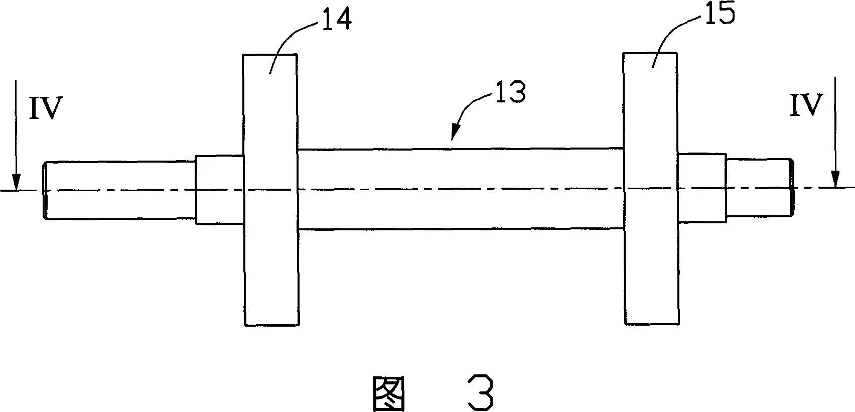
[0013] Please refer to Figure 1 and Figure 2 together. The vibration device 10 of the preferred embodiment of the present invention includes: a base plate 11, a motor 12 fixed on the base plate 11 and an electric control box 17, a main shaft 13 connected to the motor 12, a main shaft 13 arranged on the main shaft 13 The first eccentric wheel 14 and a second eccentric wheel 15 , and a vibration table 16 located on the first eccentric wheel 14 and the second eccentric wheel 15 . The motor 12 can drive the main shaft 13 to drive the first eccentric wheel 14 and the second eccentric wheel 15 to rotate, so that different parts of the first eccentric wheel 14 and the second eccentric wheel 15 alternately abut against the vibrating table 16 and make the vibrating table 16 vibrate.

[0014] The base plate 11 is a square chrome-plated steel plate, and the base plate 11 is provided with a motor fixing plate 122, a backing plate 133 and two spaced relative support plates 134 and two arms...


PUM


Abstract

A vibrating apparatus is composed of a driver, a mainshaft driven by said driver, two eccentric wheel fixed to said mainshaft and driven by the mainshaft to rotate, and a vibrating platform on said eccentric wheels and driven by them.

Description

【Technical field】 [0001] The invention relates to a vibrating device, in particular to a vibrating device for vibrating impurities. 【Background technique】 [0002] The inks or coatings used in the printing and coating industry often contain some oily impurities. The existence of these oily impurities will lead to the appearance of poor printing or coating products. Therefore, before using these inks or coatings, shake and vibrate the ink Or the container of the paint, so that some oily impurities in the ink or paint float to the surface, and then remove these impurities. [0003] However, the above-mentioned vibration removal process is done manually, the labor intensity is high, the vibration frequency is low, and the effect is not good, and some containers containing ink or paint are relatively large in volume and quality, so it is difficult to complete the vibration removal process by manpower. 【Content of invention】 [0004] In view of the above situation, it is neces...

Claims


Application Information

Patent Timeline
IPC IPC(8): B06B1/16
Inventor 黄大清杨万海
Owner SHENZHEN FUTAIHONG PRECISION IND CO LTD
Learn More