Multi-cylinder rotary compressor

A technology of rotary compressor and compression mechanism, applied in the direction of elastic fluid rotary piston type/oscillating piston type pump combination, mechanical equipment, machine/engine, etc., which can solve the troublesome processing of eccentric rollers, poor assembly, and reliability and performance side effects

Inactive Publication Date: 2007-04-18
TOSHIBA CARRIER CORP
View PDF1 Cites 36 Cited by
  • Summary
  • Abstract
  • Description
  • Claims
  • Application Information

AI Technical Summary

Problems solved by technology

[0026] In this case, the processing of the divided eccentric roller is troublesome, and if the assembly member is not formed in the peripheral surface

Method used


Image

  • Multi-cylinder rotary compressor
  • Multi-cylinder rotary compressor
  • Multi-cylinder rotary compressor

Examples


Embodiment Construction

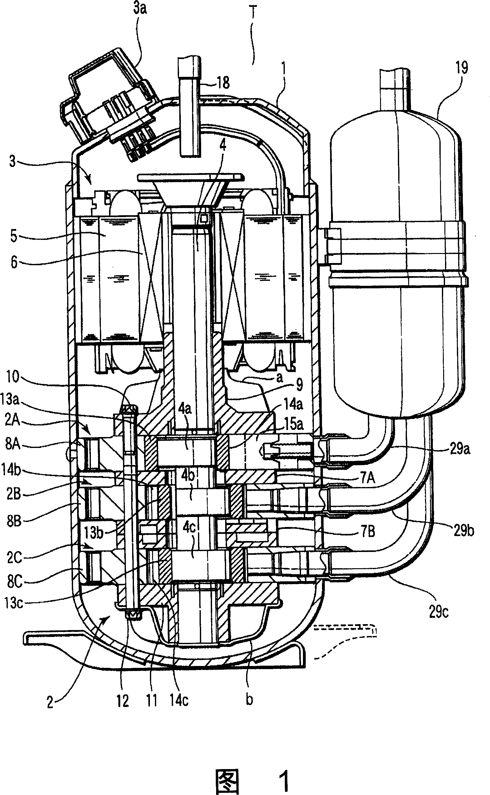
[0057] Next, one embodiment of the multi-cylinder rotary compressor of the present invention will be described with reference to the drawings. FIG. 1 is a longitudinal sectional view showing the internal structure of, for example, a multi-cylinder rotary compressor T constituting a refrigeration cycle of a refrigeration apparatus.

[0058] In Fig. 1, 1 is an airtight casing, and in the lower part of the airtight casing 1, a plurality of compression mechanism parts described later are provided, here by the first compression mechanism part 2A, the second compression mechanism part 2B and the third compression mechanism part. The compression mechanism assembly 2 constituted by the compression mechanism section 2C is provided with the motor section 3 on the upper portion of the compression mechanism assembly. These motor parts 3 and the first to third compression mechanism parts 2A to 2C constituting the compression mechanism assembly 2 are connected to each other by a rotary shaf...


PUM


Abstract

A multi-cylinder rotary compressor is constructed by receiving in a sealed chamber (1) a rotating shaft (4), an electric motor section (3), and first to third compression mechanism sections (2A-2C). The rotating shaft (4) is rotatably supported by bearings (9, 11). The compression mechanism sections (2A-2C) respectively have cylinder chambers (14a-14c) in which eccentric sections (4a-4c) and eccentric rollers (13a-13c) provided on the rotating shaft are received, cylinders (8A-8C) having the cylinders chambers, and blades (15a-15c) of which each head edge is in contact with the peripheral surface of the eccentric roller to partition the cylinder chamber into two. At least one of the two clearances, out of clearances in sliding sections of the compression mechanism sections, of the second compression mechanism section not in contact with the bearings is set greater than the clearances in the first and third compression mechanism sections in contact with the bearings. Run-out of the rotating shaft involved in its rotation can be reduced to improve compression efficiency.

Description

technical field [0001] The present invention relates to, for example, a multi-cylinder rotary compressor constituting a refrigeration cycle of a refrigeration device, and having three or more sets of compression mechanism parts in the axial direction. technical background [0002] For example, in the compression mechanism of a rotary compressor constituting a refrigeration cycle of a refrigeration device, an eccentric roller is accommodated in a cylinder chamber formed in the inner diameter of the cylinder, and a vane chamber is provided in the cylinder, and the vane is slidably accommodated. The front edge of the vane is pressed by the compression spring to elastically abut against the peripheral surface of the eccentric roller, and the cylinder chamber is divided into two chambers, the suction chamber and the compression chamber, by the vane. [0003] In recent years, a two-cylinder rotary compressor having two sets of the above-described compression mechanism units up and...

Claims


Application Information

Patent Timeline
IPC IPC(8): F04C23/00
Inventor 小野田泉长谷川益巳后藤进矢高坂元俊加藤久尊里馆康治青木俊公
Owner TOSHIBA CARRIER CORP
Why Eureka
Try Eureka