Driving control system for overturn row-by-row and its method and LED display screen

A technology for LED display and drive control, applied in energy-saving control technology, static indicator, semiconductor/solid-state device manufacturing, etc. Normal operation, avoid voltage noise, reduce the effect of the instantaneous change of current

Active Publication Date: 2007-05-16
深圳市中庆微科技开发有限公司
View PDF0 Cites 8 Cited by
  • Summary
  • Abstract
  • Description
  • Claims
  • Application Information

AI Technical Summary

Benefits of technology

This patented technology allows for efficient reduction of electrical power fluctuations when controlling multiple lights emitted from an array of pixels simultanously without causing any damage over time. It also improves image quality through reducing variations between different colors produced at specific points within the displayed images.

Problems solved by technology

Technological Problem addressed in this patented text relates to improving the performance (fidelity) and stability of LED displays used in displaying images without causing any instability over longer periods due to increased currents caused by multiple columns of lights emitted from individual pixel elements located next to one another. Current methods require complex wiring patterns between different parts within the panel, making it difficult to achieve desired results.

Method used


Image

  • Driving control system for overturn row-by-row and its method and LED display screen
  • Driving control system for overturn row-by-row and its method and LED display screen
  • Driving control system for overturn row-by-row and its method and LED display screen

Examples


Embodiment Construction

[0043] The present invention will be described in detail below in conjunction with the accompanying drawings.

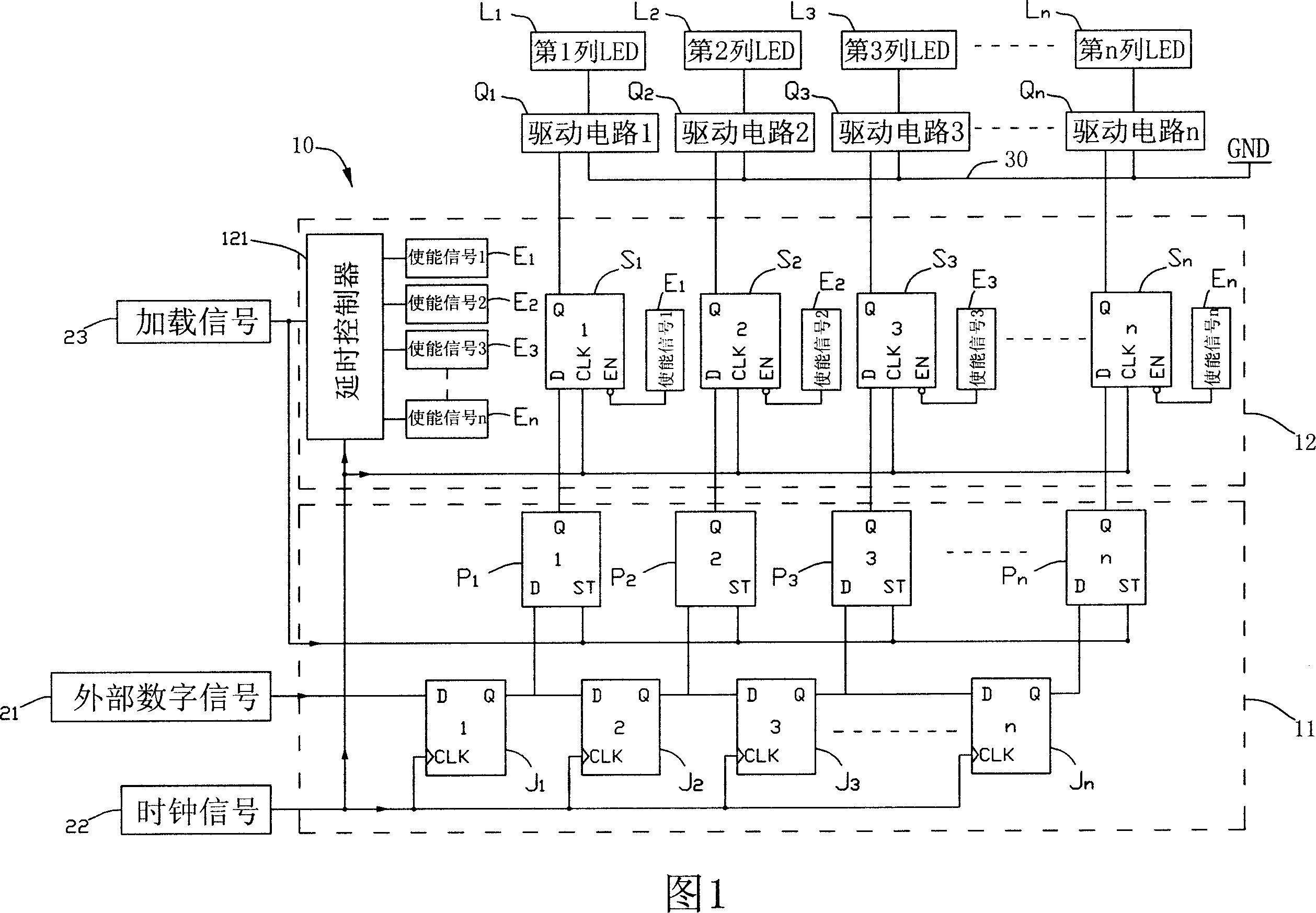
[0044] FIG. 1 is a schematic diagram of the circuit principle of the column-by-column inversion control device 12 of the present invention. In this embodiment, the column-by-column inversion control device 12 is used for an LED display screen 10, and the LED display screen 10 is mainly used for receiving external images, Signals such as text are then displayed on the LED display screen by controlling and driving the LED lights L1, L2, L3...Ln, but it is not limited to this.

[0045] The LED display screen 10 of this embodiment mainly includes several LED lamps L1, L2, L3...Ln, several driving circuits Q1, Q2, Q3...Qn, an information collection circuit 11, and a column-by-column flip control device 12, which will be described in detail below . The drive circuits Q1, Q2, Q3...Qn, the information collection circuit 11 and the column-by-column inversion control device 1...


PUM


Abstract

This invention relates to one turnover drive control system and its method and LED display screen, wherein, the system comprises turnover control devices to control several digital output signal each basic circle by one or several clock signal into drive circuit of relative light element; the control system can effectively lower drive circuit current prompt changes range to lower voltage noise.

Description


Claims


Application Information

Patent Timeline
Owner 深圳市中庆微科技开发有限公司
Why Eureka
Try Eureka