
Driving control system for overturn row-by-row and its method and LED display screen

A technology of LED display and flip control, applied in energy-saving control technology, static indicators, semiconductor/solid-state device manufacturing, etc., can solve the problems of large instantaneous current changes, low hardware utilization, voltage noise, etc., and achieve instantaneous reduction of current Variation amplitude, avoiding voltage noise, and ensuring normal operation

Active Publication Date: 2010-05-12
深圳市中庆微科技开发有限公司
View PDF5 Cites 0 Cited by
  • Summary
  • Abstract
  • Description
  • Claims
  • Application Information

AI Technical Summary

Problems solved by technology

However, this design has major disadvantages: complex circuits, low hardware utilization, and high cost
And the column is opened for a short time, generally 200 nanoseconds or a little more
[0005] In a short period of time, the greater the current change, it is easy to cause voltage noise, resulting in large fluctuations in the voltage on the final ground bus
The fluctuating state of this voltage can easily lead to the failure of the working voltage of the circuit components, and it is easy to make the whole circuit unable to work normally, because the final ground bus is generally the voltage reference of other circuit components
Specific to the LED display, it is easy to cause the change of the working voltage of the LED. The change of the working voltage directly leads to the change of the current flowing through the LED, which affects the normal light emission of the LED, and even produces the disadvantage of not being able to emit light, which greatly affects the display of the LED display. Effect
[0006] With the advancement of LED display technology, there are more and more pixels on the same area unit board, that is to say, the number of LED columns on the same area unit board also increases; and the LED display screen is also getting larger and larger, so that As a result, the instantaneous current changes are also increasing, so the technology of turning on the corresponding column LEDs at the same time as the existing column drive circuit has greatly hindered the development of LED display technology.

Method used


Image

  • Driving control system for overturn row-by-row and its method and LED display screen
  • Driving control system for overturn row-by-row and its method and LED display screen
  • Driving control system for overturn row-by-row and its method and LED display screen

Examples


Embodiment Construction

[0043] The present invention will be described in detail below in conjunction with the accompanying drawings.

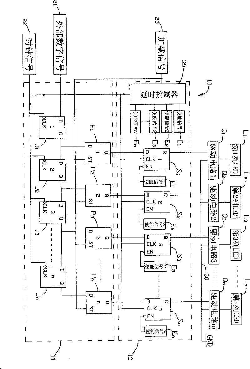
[0044] figure 1 Shown is a schematic diagram of the circuit principle of the column-by-column inversion control device 12 of the present invention. In this embodiment, the column-by-column inversion control device 12 is used for the LED display screen 10, and the LED display screen 10 is mainly used for receiving external images, characters, etc. The signal is then controlled to drive the LED lamps L1, L2, L3...Ln to be displayed on the LED display screen, but it is not limited thereto.

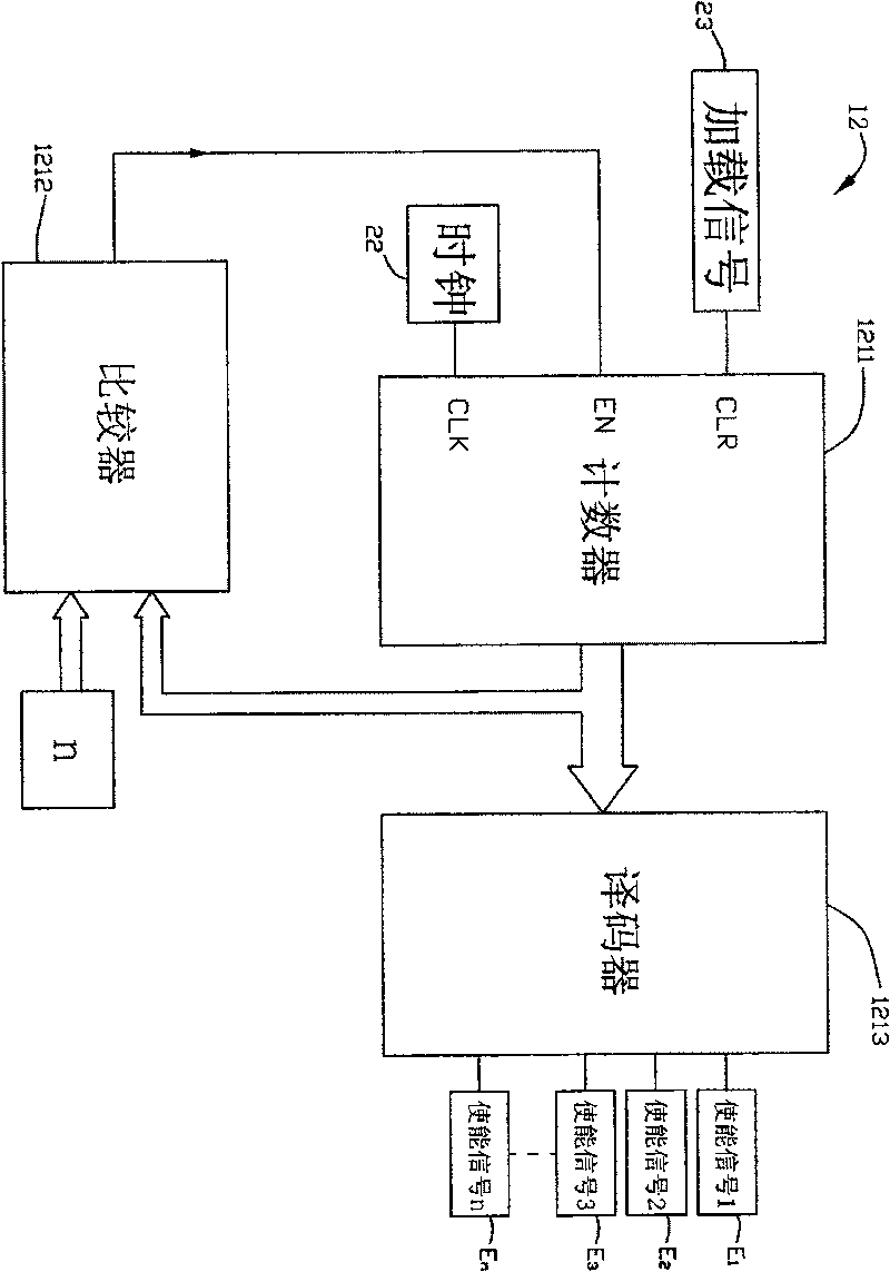
[0045] The LED display screen 10 of this embodiment mainly includes several LED lamps L1, L2, L3...Ln, several driving circuits Q1, Q2, Q3...Qn, an information collection circuit 11, and a column-by-column flip control device 12, which will be described in detail below . The drive circuits Q1, Q2, Q3...Qn, the information collection circuit 11 and the column-by-column inversion co...


PUM


Abstract

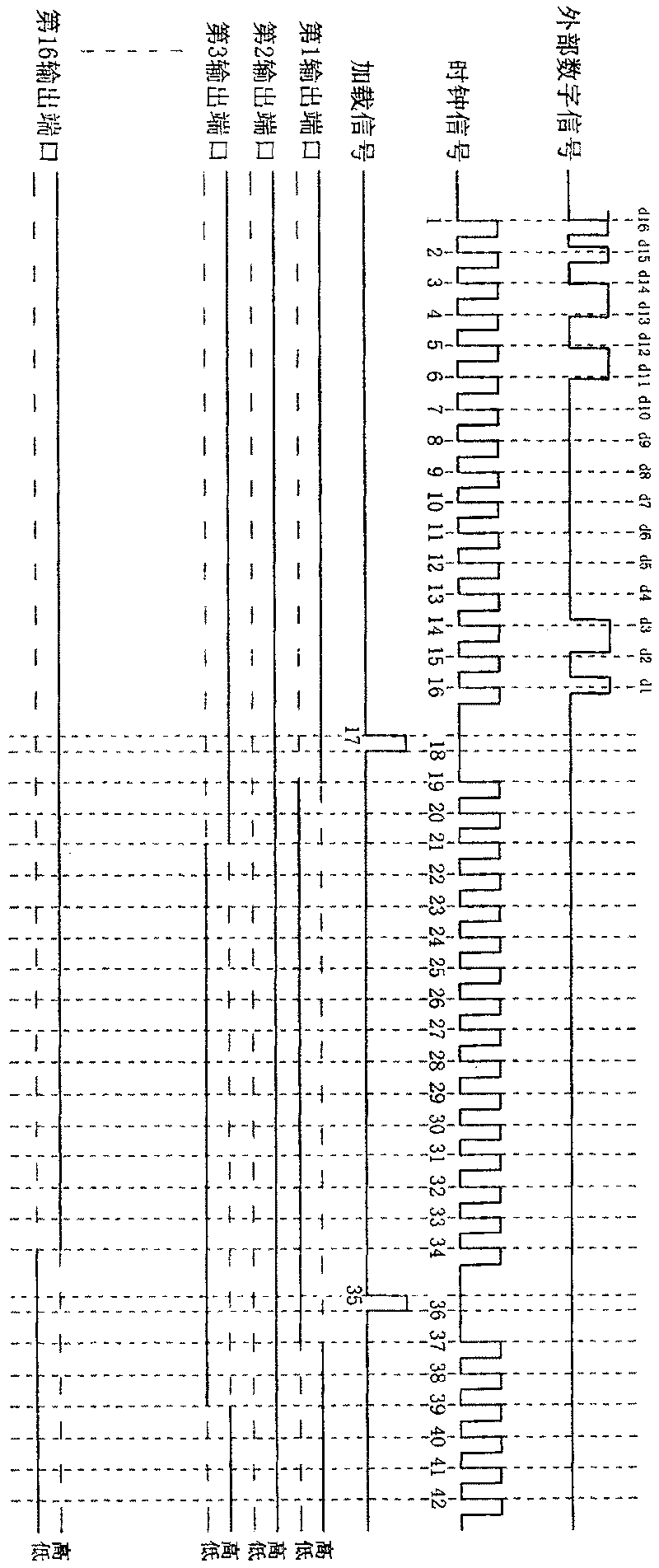
This invention relates to one turnover drive control system and its method and LED display screen, wherein, the system comprises turnover control devices to control several digital output signal eachbasic circle by one or several clock signal into drive circuit of relative light element; the control system can effectively lower drive circuit current prompt changes range to lower voltage noise.

Description

【Technical field】 [0001] The invention relates to a column-by-column flip drive control system and method, in particular to a column-by-column flip drive control system and method for LED display screens. 【Background technique】 [0002] At present, LED displays can generally be divided into static and scanning according to the display control method. Static display means that each LED in the LED electronic display is controlled individually by hardware, and all LEDs in the entire LED display are controlled at the same time. The biggest advantage of this method is that the program design is simple and the screen does not flicker. However, there are major disadvantages in this design: the circuit is complicated, the hardware utilization rate is low, and the cost is high. [0003] With the advancement of LED manufacturing technology, the brightness of LED has been significantly improved. At present, more and more LED display screens use dynamic scanning to realize the display...

Claims


Application Information

Patent Timeline
Patent Type & Authority Patents(China)
IPC IPC(8): G09G3/32G09G3/30G09G3/20H05B33/08H05B33/14H05B37/02H01L51/50H01L27/32H05B44/00
CPCY02B20/42Y02B20/40
Inventor 邵寅亮
Owner 深圳市中庆微科技开发有限公司
Learn More