Branch duct mixer

A technology of mixers and branch pipes, which is applied in the direction of fluid mixers, mixers, chemical instruments and methods, etc., can solve the problems of influence, poor quality and yield of semi-coke and coal tar, and the inability to achieve uniform heating of coal, etc., to achieve heating The effect of gas uniformity

Inactive Publication Date: 2007-05-23
SHAANXI SHENMU SAN JIANG COAL CHEM
View PDF0 Cites 2 Cited by
  • Summary
  • Abstract
  • Description
  • Claims
  • Application Information

AI Technical Summary

Problems solved by technology

[0002] The heating gas of the existing coal carbonization furnace is directly input into the furnace cavity through the gas pipeline and the air pipeline, so the distribution

Method used


Image

  • Branch duct mixer
  • Branch duct mixer
  • Branch duct mixer

Examples


Embodiment Construction

[0013] The present invention will be described in further detail below in conjunction with the accompanying drawings and specific embodiments, but not as a limitation of the present invention.

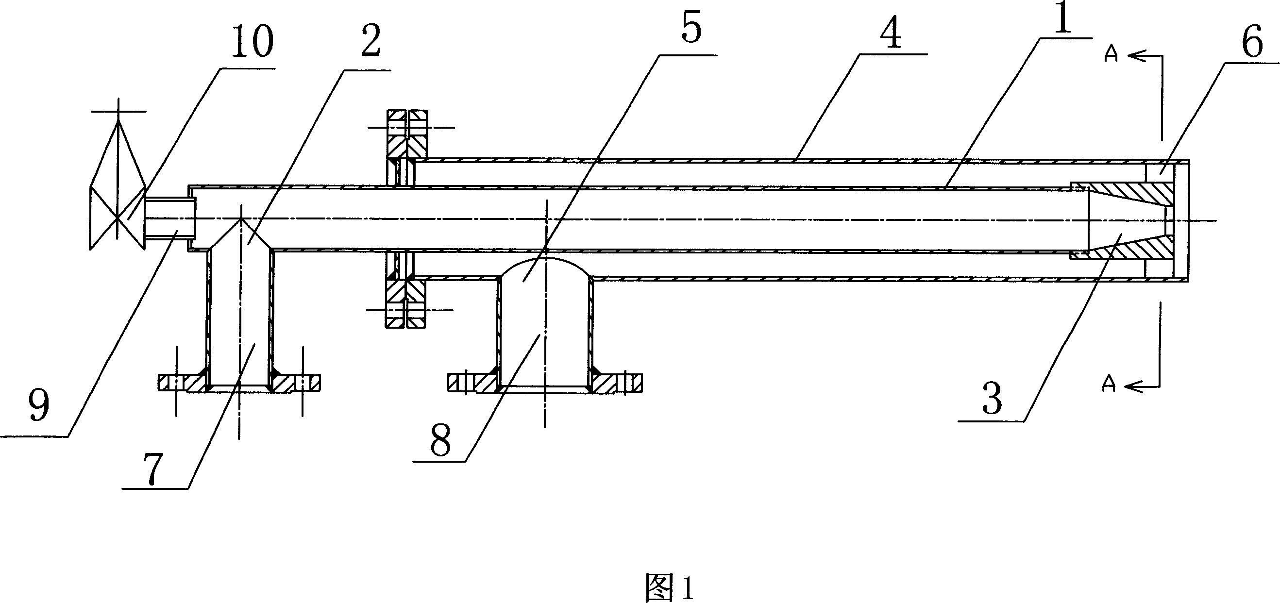
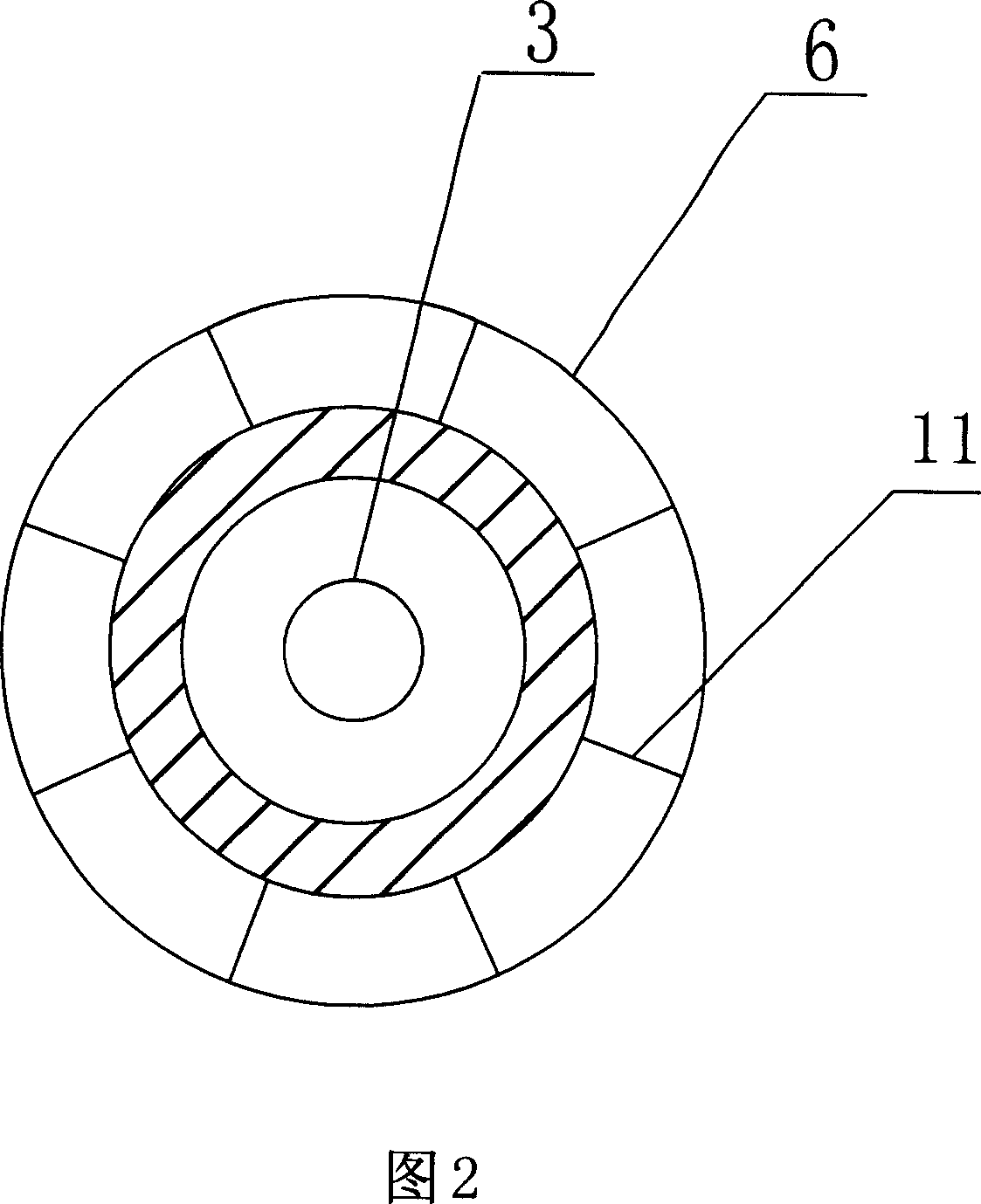
[0014] As shown in Figure 1, a branch pipe mixer includes an inner pipe 1, an inner pipe interface 2, an inner pipe nozzle 3, an outer pipe 4, an outer pipe interface 5, an outer pipe nozzle 6, an air main pipe interface pipe 7, and a gas main pipe interface Pipe 8, peephole 9 and ball valve 10, wherein the outer pipe 4 is set outside the inner pipe 1 to form a double-layer steel pipe structure, one end of the inner pipe 1 is the inner pipe nozzle 3, and the inner pipe nozzle 3 is a variable diameter structure welded to the inner pipe 1 front end, the caliber of the connection between the variable diameter structure and the inner tube 1 is larger than the caliber of the spout, and the other end is connected with a peep hole 9, and the end of the outer tube 4 corresponding to the inner t...


PUM


Abstract

The invention relates to a branch mixer, wherein the inner tube is sheathed with outer tube to form dual-layer steel tube structure; one end of inner tube is the ejector, while one relative end of outer tube is ejector; another end near the outer tube has outer tube connector on the side wall; the outer tube connector is connected to the main gas tube connector. The invention has simple structure; the high-pressure air of inner tube is high-speed ejected from the inner tube ejector, to eject the gas in outer tube at high speed, to be mixed uniformly to be ejected into furnace, to uniformly distribute the heating gas in retort furnace.

Description

technical field [0001] The invention relates to a mixer, in particular to a branch tube mixer used in a low-temperature carbonization furnace for mixing heating gases and uniformly feeding them into the furnace. Background technique [0002] The heating gas of the existing coal carbonization furnace is directly input into the furnace cavity through the gas pipeline and the air pipeline, so the distribution of the input gas in the raw coal is not uniform, so the uniform heating of the coal cannot be realized. It will have adverse effects on the quality and yield of semi-coke and coal tar. Contents of the invention [0003] In order to solve the above-mentioned problems, the object of the present invention is to provide a branch pipe mixer for uniformly mixing the heating gas of the low-temperature carbonization furnace on the same level in the furnace and forming a high-speed air flow into the furnace. [0004] Technical scheme of the present invention is realized like thi...

Claims


Application Information

Patent Timeline
IPC IPC(8): B01F5/02C10B21/00
Inventor 尚文智王茂义辛绍兵
Owner SHAANXI SHENMU SAN JIANG COAL CHEM
Why Eureka
Try Eureka