
Spiral hollow coil current transformer with compensating coils

A technology of current transformers and hollow coils, applied in the direction of inductors, instruments, circuits, etc., can solve the problems that electromagnetic current transformers are susceptible to electromagnetic interference, coil resistance, area, volume increase, and increase mutual inductance coefficient, etc., to achieve Improve measurement accuracy and anti-electromagnetic interference ability, improve saturation characteristics and linearity, and ensure the effect of measurement accuracy

Inactive Publication Date: 2011-02-16
长沙同庆电气信息有限公司
View PDF0 Cites 0 Cited by
  • Summary
  • Abstract
  • Description
  • Claims
  • Application Information

AI Technical Summary

Problems solved by technology

[0003] The electromagnetic current transformer is composed of an iron core and primary and secondary windings. Its main disadvantages are: 1. The requirements for insulation technology are complicated, and it is flammable and explosive.
2. The dynamic range is small, the frequency band is narrow, and the error is large
3. High cost
For the ultra-high voltage electromagnetic current transformer, due to the complexity of its insulation method and the consumption of materials, it results in a large volume, a substantial increase in production costs, and also brings difficulties to transportation.
4. Added strict requirements on the secondary side
6. Electromagnetic current transformers also have disadvantages such as being susceptible to electromagnetic interference, heavy maintenance workload, and oil leakage polluting the environment.
These two air-core coil current sensors have two main disadvantages: (1) The coupling between the primary conductor and the secondary coil is weak, so that the mutual inductance coefficient is small, and it is difficult to increase the mutual inductance coefficient by increasing the number of coil turns and the area, otherwise it will cause the coil Increased resistance, area, and volume; (2) susceptible to external interference magnetic fields; in addition, the ring skeleton is not convenient for uniform and tight winding of the sensing coil, which will also affect the measurement accuracy and anti-electromagnetic interference
Due to the above shortcomings, when the existing air-core coil current sensing technology is used to measure the three-phase current of the power system, the current measurement of one phase will be interfered by the electromagnetic field generated by the other two-phase current, especially when measuring small currents (power system light load), the induction signal is weak, and it is easily disturbed by the external magnetic field, resulting in a large measurement error

Method used


Image

  • Spiral hollow coil current transformer with compensating coils
  • Spiral hollow coil current transformer with compensating coils
  • Spiral hollow coil current transformer with compensating coils

Examples


Embodiment Construction

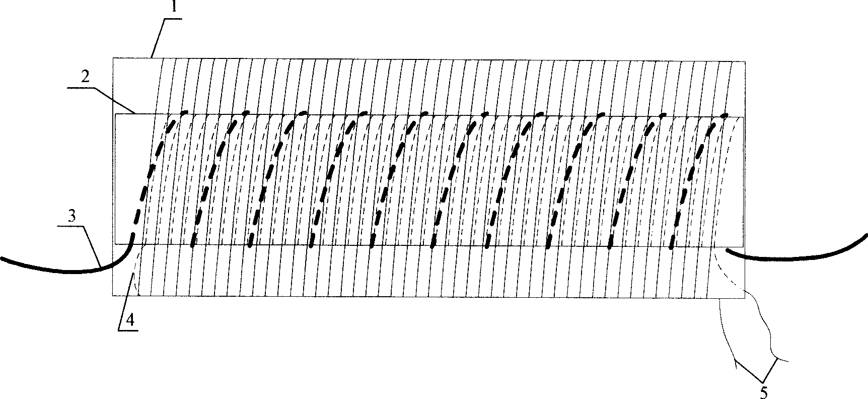
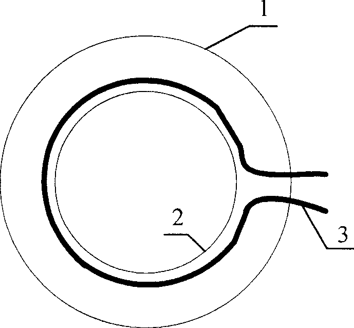
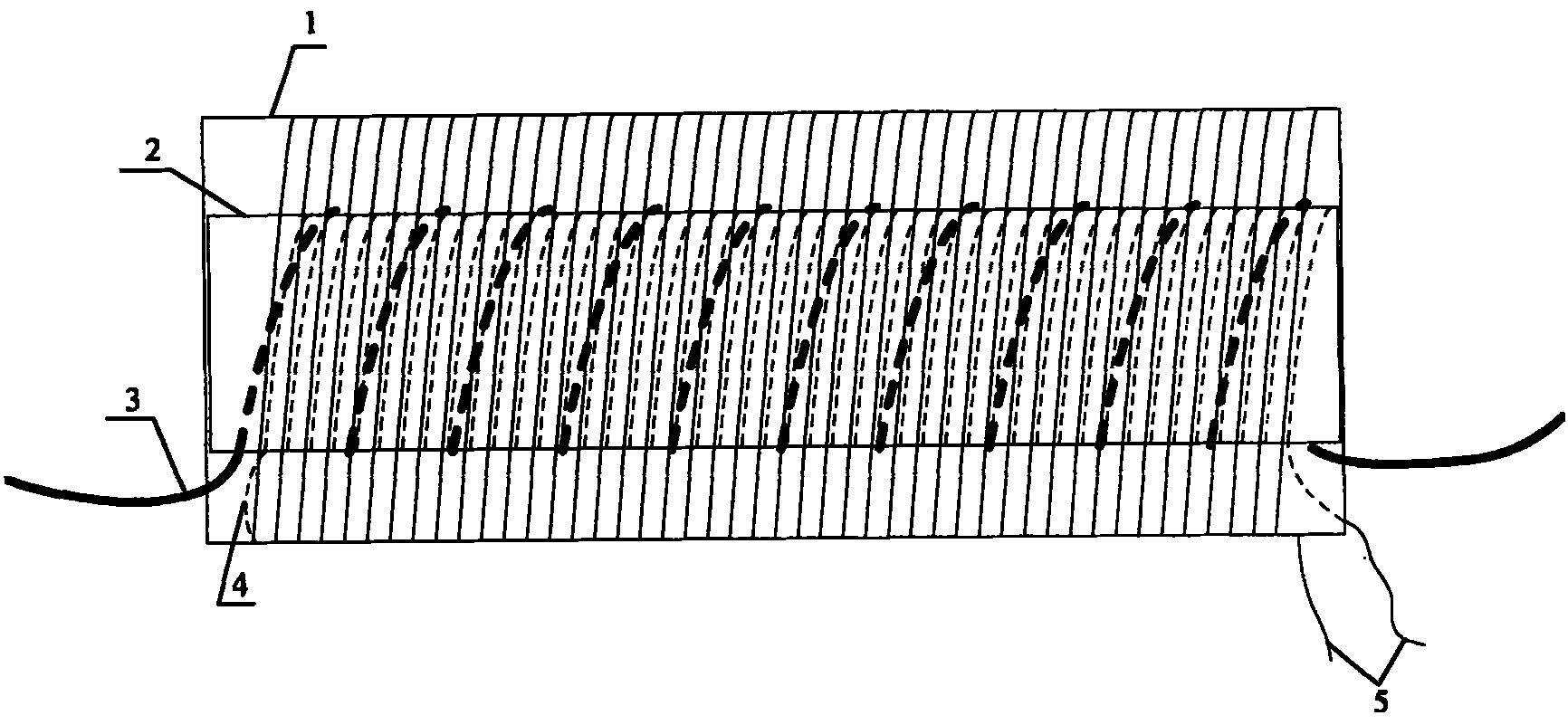
[0014] see figure 1 , figure 2 , figure 1 It is a structural schematic diagram of an embodiment of the present invention. 2 in the figure is the secondary helical tube sensing coil, and 1 is the secondary compensation helical tube hollow coil to offset the external magnetic field interference. The two are uniformly and tightly wound by the same enamelled thin copper wire to form a helical tube with the same length. Each layer The number of turns of the coils is the same, and the winding direction of the two coils is the same, the head end or the end is connected, there is one layer of hollow coils on the spiral 1, and there are three layers of hollow coils on the spiral 2. 3 is a primary helical tube coil, which is tightly wound around the helical tube sensing coil 2 to form a helical tube, so that the secondary sensing coil can be more strongly coupled to the primary coil, which facilitates the improvement or reduction of the mutual inductance coefficient, and can meet the...


PUM


Abstract

The invention discloses a kind of helical pipe hollow coil current transformer with compensation coil, including two sets of internal and external straight-shaped non-magnetic frame and the first coil, the second sensing coil, the second compensation coil, and the second compensation coil uniformly and closely surrounds the external non-magnetic frame, the second sensing coil uniformly and closely surrounding the internal non-magnetic frame, the first coil closely windingly surrounding the second sensing coil. The second sensing coil and the second compensation coil connect according to the limited mode of the winding direction, the other two ends not connected, as the export end of the second sensing signals. The invention obvious improves the transient nature and linear rate of the current transformer, greatly increases the measurement precision and electromagnetic-resistance interference ability, suitable for the production of sensor head of electronic current transformer, and alsocan be used to produce the current sensor for secondary measurement, monitoring and computer protection devices of conventional current transformer.

Description

technical field [0001] The invention relates to a current transformer, in particular to a spiral tube hollow coil current transformer with a compensation coil for measurement and protection in a power system. Background technique [0002] At present, the current transformers used in power systems are mainly electromagnetic current transformers. In order to meet the needs of power system development and power system automation and digitization, current transformers using other induction principles have also been developed at home and abroad. According to the selection of the sensor head, it is mainly divided into two types: pure optical current transformer based on the Faraday magneto-optical effect principle and electronic current transformer based on Rogowski (hollow) coil. [0003] The electromagnetic current transformer is composed of an iron core and primary and secondary windings. Its main disadvantages are: 1. The technical requirements for insulation are complicated,...

Claims


Application Information

Patent Timeline
Patent Type & Authority Patents(China)
IPC IPC(8): G01R15/00H01F38/28
Inventor 周有庆龚伟吴桂清彭红海
Owner 长沙同庆电气信息有限公司
Learn More