Resistor for controlling load circuit and its assembly method and wiring board

A load current and resistor technology, applied in excitation or armature current control, other resistor networks, resistor terminals/electrodes, etc., can solve the problems of assembly process or man-hours and the number of components, and achieve the effect of compact length

Inactive Publication Date: 2007-05-23
DENSO CORP
View PDF1 Cites 1 Cited by
  • Summary
  • Abstract
  • Description
  • Claims
  • Application Information

AI Technical Summary

Problems solved by technology

[0008] Therefore, in the above-mentioned Patent Document 1, there is a problem

Method used


Image

  • Resistor for controlling load circuit and its assembly method and wiring board
  • Resistor for controlling load circuit and its assembly method and wiring board
  • Resistor for controlling load circuit and its assembly method and wiring board

Examples


other Embodiment approach

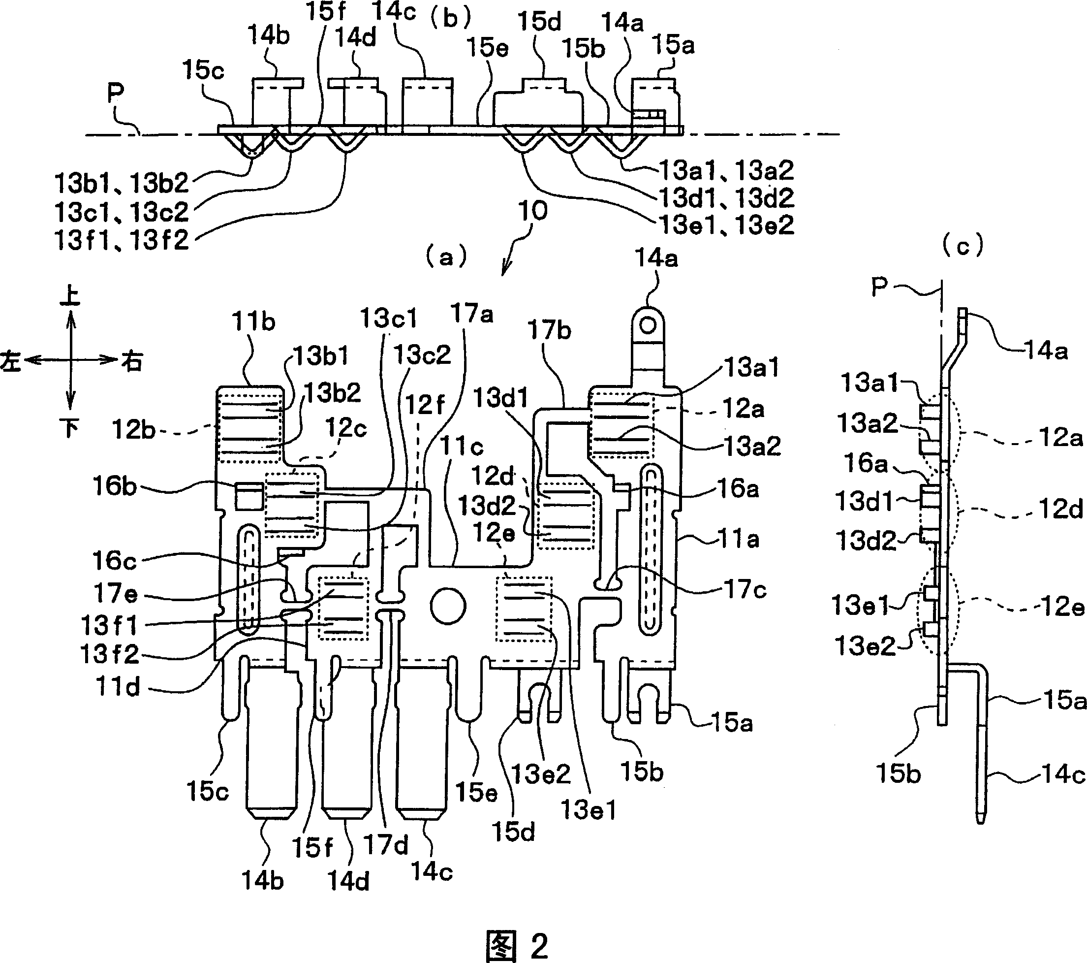
[0103] (1) In the above-mentioned present embodiment, in order to make the first to sixth flat plate parts 12a to 12f of the lead parts 20a to 22b fixing the three resistors 20 to 22 all be located on the same plane P, the 40 is an example in which the first to fourth wiring members 11a to 11d are arranged in a row in the horizontal direction, but the present invention is not limited thereto.

[0104] That is, for example, it may be arranged such that only the two flat plate parts 12e, 12f of the pair of lead parts 22a, 22b fixing the third resistor 22 are located on the same plane, and the pair of lead parts 21a, 21b of the second resistor 21 are fixed on the same plane. The two flat plate parts 12c, 12d are located on another same plane parallel to the above-mentioned plane. Furthermore, the two flat plate parts 12a, 12b which fix the pair of lead part 20a, 20b of the 1st resistor 20 can also be arrange|positioned so that it may be located on another same plane similarly. A...


PUM


Abstract

The present invention provides a resistor used for controlling load current with reduced assembly procedure or man-hour and components amount thereof. A patch board with a unitary structure made of four connection parts 11a-11d which bridge parts are connected to each other in advance is prepared. The bridge parts are removed after the patch board of the 1 part is assembled and fixed on the base 40. Then the four connection parts are arranged separately in a row in the landscape orientation on the base. Each connection part is provided with flat plate parts 12a-12f which form the connection parts 13a1-13f2 of conductor parts 20a-20b used for fixed resistors 20-22, wherein these flat plate parts are positioned on the same plane. After each conductor part is inserted to a bore which is formed by pricking up of each connection part from flat plate parts, a fixation and an electronic connection are performed by fullering along with all the others. Thereby the number of components for assembling and the fixed hours for the resistors are reduced.

Description

technical field [0001] The present invention relates to a resistor for load current control, a terminal board used therefor, and an assembly method for the resistor for load current control. The resistor for load current control of the present invention is suitably used as a resistor for speed control of an air blower or the like. Background technique [0002] Conventionally, as a device for switching the blowing air volume of an air conditioner, there is a speed control resistor. This resistor for speed control is a resistor for load current control with a plurality of resistors connected in series. By selecting the resistor to be used with a switch, the voltage applied to the blower motor is changed to adjust the load current, that is, the air flow rate (for example, refer to Patent Document 1). [0003] Such a resistor for speed control requires one less resistor than the number of switching stages of the air flow rate. Furthermore, since these resistors are independent...

Claims


Application Information

Patent Timeline
IPC IPC(8): H01C1/14H01C1/16H05K7/02H02P7/14
Inventor 并河晃人早矢仕修
Owner DENSO CORP
Why Eureka
Try Eureka