Baffle assembly for modifying transitional flow effects between different cavities

a technology of transitional flow and assembly, which is applied in the direction of burners, combustion types, combustion processes, etc., can solve the problems of different properties of the produced flame proximate to the fuel inlet, and achieve the effect of improving the operation of gas burners and other systems

Active Publication Date: 2018-12-20
SELAS HEAT TECH
View PDF0 Cites 1 Cited by
  • Summary
  • Abstract
  • Description
  • Claims
  • Application Information

AI Technical Summary

Benefits of technology

[0005]The present disclosure is directed to a baffle assembly for modifying the entrance and / or transitional effects of fluid flows, such as for improving the operation of gas burners and other systems.

Problems solved by technology

Referring back to gas burners (particularly ribbon burners that are arranged to produce a flame along a length of the burner), the entrance effects introduced by the transition from the fuel inlet into the burner cavity can create an issue in which the properties of the produced flame proximate to the fuel inlet differ from the properties of the flame at distances further away from the fuel inlet.

Method used


Image

  • Baffle assembly for modifying transitional flow effects between different cavities
  • Baffle assembly for modifying transitional flow effects between different cavities
  • Baffle assembly for modifying transitional flow effects between different cavities

Examples


Embodiment Construction

[0018]A description of example embodiments of the invention follows.

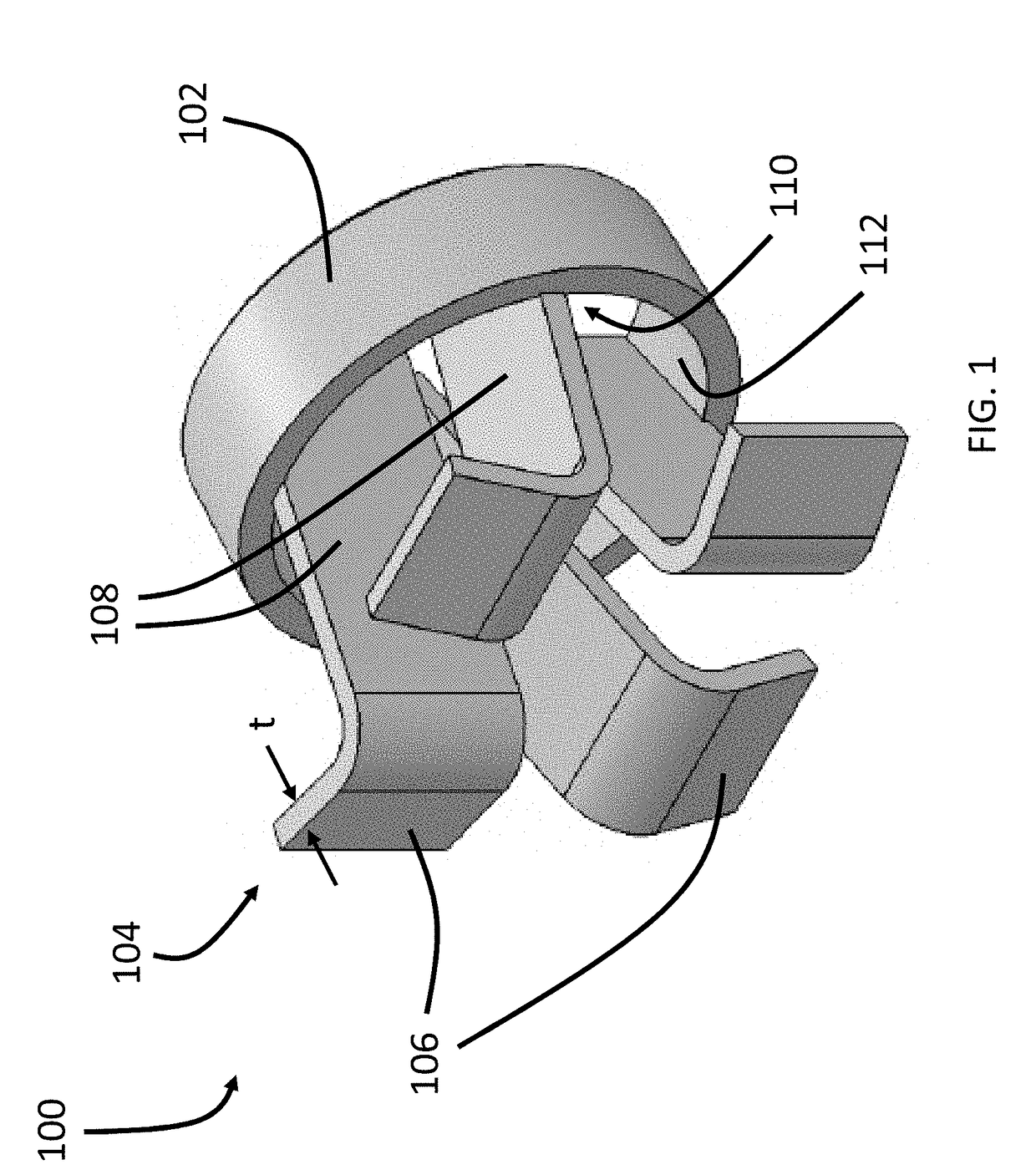
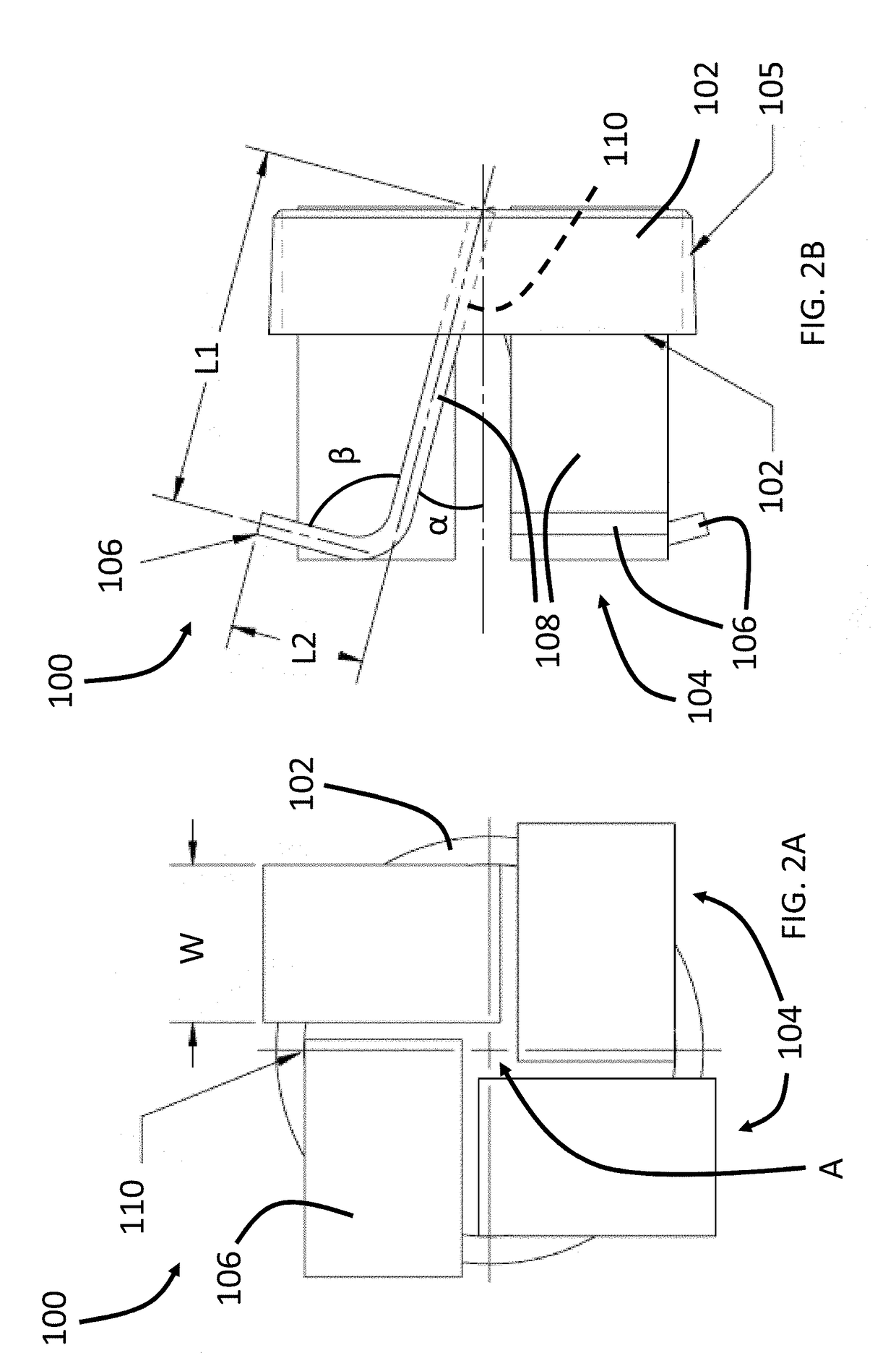
[0019]A perspective view of a baffle assembly is shown in FIG. 1, in accordance with an embodiment. FIGS. 2A and 2B are respective front and side views of the assembly of the baffle assembly of FIG. 1. The following should be viewed based on FIGS. 1-2B.

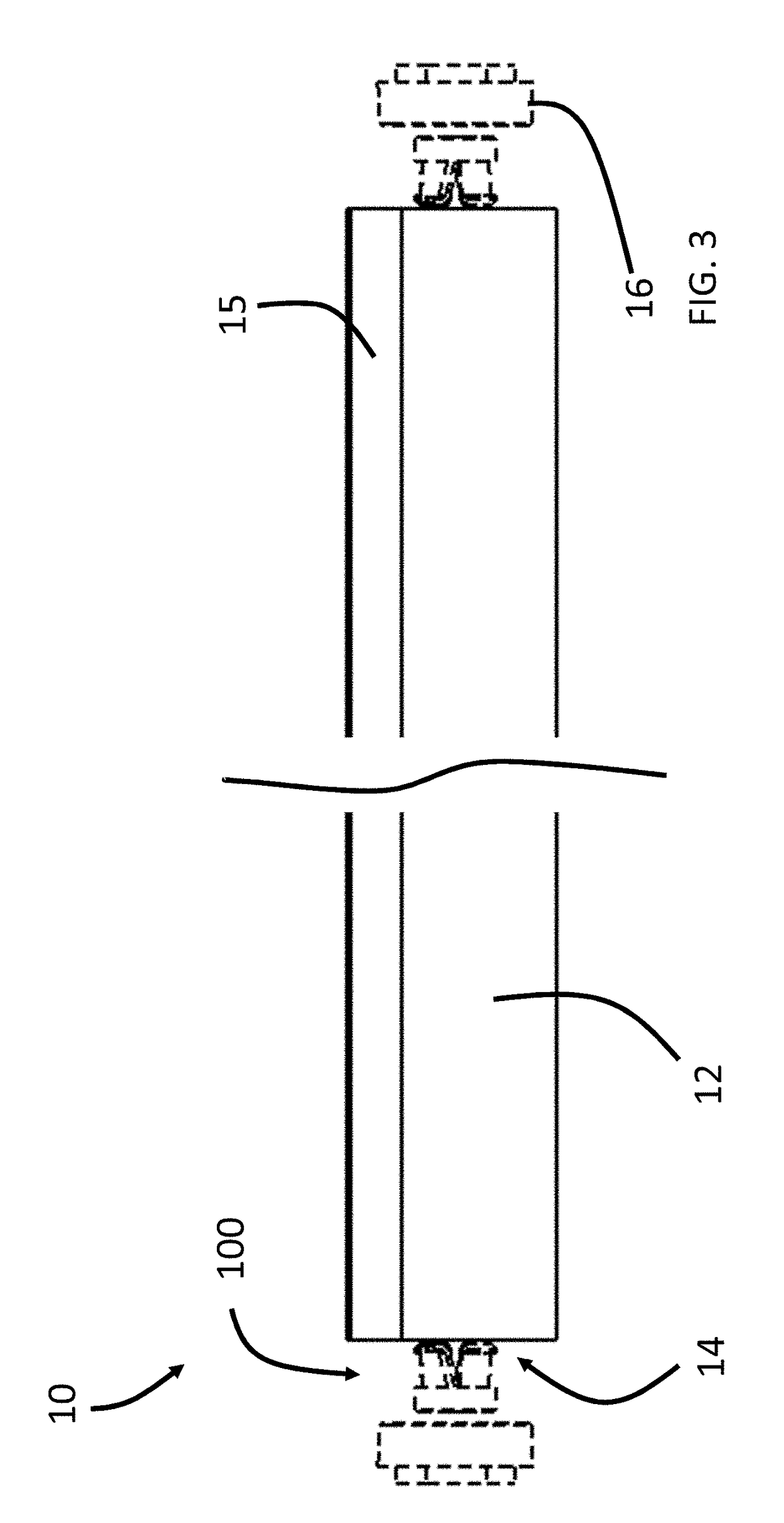
[0020]The baffle assembly 100 generally includes a hub or collar 102 having a plurality of vanes 104 secured thereto. As discussed in more detail below, the vanes 104 of the baffle assembly 100 are arranged to reduce entrance effects and / or transitional effects on the fluid flow as the flow of a fluid transitions between different sized, shaped, structured, and / or oriented flow cavities. For example, the baffle assembly 100 may be positioned at, in, or near the transition of a pipe or cavity having a relatively larger cross-sectional flow area into a pipe or cavity having a relatively smaller cross-sectional flow area. Namely, the baffle assembly 100 can be used to cr...


PUM


Abstract

A baffle assembly and burner including the baffle assembly. The baffle assembly includes a collar having a central axis and an inner circumferential surface. A plurality of vanes are secured to the inner circumferential surface of the collar. Each vane includes a leg extending from the collar at a first angle with respect to the central axis. The first angle of the leg is configured to impart rotation to a flow of fluid through the baffle assembly. An impingement plate extends from the leg at a second angle with respect to the central axis. The second angle is greater than the first angle.

Description

CROSS-REFERENCE TO RELATED APPLICATIONS[0001]This application claims the benefit of U.S. Provisional Patent Application Ser. No. 62 / 521,861, filed on Jun. 19, 2017 and entitled “BURNER BAFFLE FOR IMPROVING FLAME UNIFORMITY”, the entire disclosure of which is incorporated herein by reference.FIELD OF THE INVENTION[0002]The present disclosure relates generally to a baffle assembly, and more specifically, to a baffle assembly to modify the effects on fluid flow while transitioning between different cavities, which can be utilized in a variety of industries including gas burners.BACKGROUND[0003]A variety of tools, systems, and assemblies require the supply of fluid or gaseous mixtures. For example, gas burners are utilized to generate a flame to heat a product using a gaseous fuel such as acetylene, natural gas, and / or propane, among other fuel sources. e.g., air-gas mixtures may be utilized as fuel for gas powered burners. In gas burners and other applications, the fluid may transition...

Claims


Application Information

Patent Timeline
Patent Type & Authority Applications(United States)
IPC IPC(8): F15D1/02F23D14/58
CPCF15D1/025F23D14/586F23D14/70F15D1/02F15D1/0005F23D14/62
Inventor MATHIS, STEVEVANDEGRIFT, CHRIS E.SU, GUOGUANG
Owner SELAS HEAT TECH
Why Eureka
Try Eureka