Feeding device of chip mounter

A feeding device and placement machine technology, applied in the direction of electrical components, electrical components, etc., can solve the problems of low transportation efficiency, high manufacturing cost, complex structure, etc., and achieve cost and failure rate reduction, high transmission efficiency, and compact length Effect

Pending Publication Date: 2018-07-24
罗伊力尔(苏州)智能科技有限公司
View PDF0 Cites 1 Cited by
  • Summary
  • Abstract
  • Description
  • Claims
  • Application Information

AI Technical Summary

Problems solved by technology

[0006] The technical problem to be solved by the present invention is to provide a chip mounter feeding device, which can solve the problems of complex structure, low transportation efficiency and high manufacturing cost in the prior art.

Method used


Image

  • Feeding device of chip mounter
  • Feeding device of chip mounter
  • Feeding device of chip mounter

Examples


Embodiment Construction

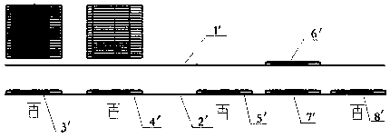
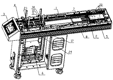
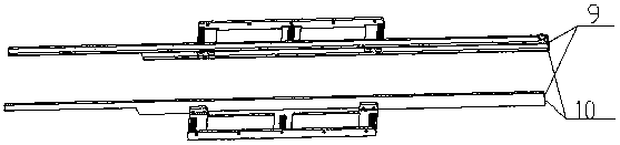
[0031] Such as figure 2 As shown, a chip mounter feeding device includes a conveying track 1, a conveying handle 2 and a controller 3, the conveying handle 2 reciprocates between the two ends of the conveying track 1, and the two ends of the conveying track 1 are provided with upper Material mechanism 4 and unloading mechanism 5, the bottom of loading mechanism 4 is provided with recovery mechanism 6, between loading mechanism 4 and unloading mechanism 5, be provided with waiting material cache mechanism 7 and recovery cache mechanism 8, recovery cache mechanism 8 is located at Just below the material buffer mechanism 7. Such as image 3 As shown, the transport track 1 includes an upper transport track 9 and a lower transport track 10 . Such as Figure 4As shown, the feeding mechanism 4 is located above the upper conveying track 9, including a feeding platform 11, a material receiving block 12, and a feeding lifting platform 13. The material receiving block 12 is located a...


PUM


Abstract

The invention discloses a feeding device of a chip mounter. The feeding device comprises a transmission rail, a loading mechanism, an unloading mechanism, a recycling mechanism, a material to be waited buffer storage mechanism, a recycling buffer storage mechanism and a transmission grabber, wherein the transmission rail comprises an upper-layer transmission rail and a lower-layer transmission rail, the loading mechanism and the unloading mechanism are respectively arranged at two ends of the transmission rail, the recycling mechanism is arranged below the loading mechanism, the material to bewaited buffer storage mechanism is arranged on the upper-layer transmission rail, the recycling buffer mechanism is arranged on the lower-layer transmission rail, and the transmission grabber 2 movesin a reciprocating way between the two ends of the transmission rail under driving of a power device. By the feeding device of the chip mounter, the recycling mechanism is arranged below the loadingmechanism, and a recycling descending mechanism is omitted; and a cycle transmission mode that the upper-layer transmission rail is used for feeding and the lower-layer transmission rail is used for recycling is employed, the length of the whole machine is more compact, a transmission path of the transmission grabber is more simplified, the material disc transmission efficiency is improved, and the cost and the fault ratio of the whole machine are remarkably reduced.

Description

technical field [0001] The invention relates to the field of surface mounting in the manufacture of electronic products, in particular to a feeding device for a placement machine. Background technique [0002] At present, the placement machines used in the field of surface mounting of electronic products at home and abroad need to be used with the feeding device of the placement machine. The function of the feeding device of the placement machine is to deliver the tray to the pick-up port of the placement machine. [0003] Such as figure 1 As shown, in the prior art, the feeding device of the placement machine mainly includes: a feeding mechanism 3', a feeding mechanism 8', a material buffer mechanism 7', a recovery buffer mechanism 6', a recovery lowering mechanism 5', a recovery mechanism 4 ', the clamping device, the feeding mechanism 3' and the unloading mechanism 8' are respectively set at the two ends of the conveying track, the conveying track includes the upper co...

Claims


Application Information

Patent Timeline
Patent Type & Authority Applications(China)
IPC IPC(8): H05K13/02
CPCH05K13/02
Inventor 王胜月郑江俞林
Owner 罗伊力尔(苏州)智能科技有限公司
Why Eureka
Try Eureka