
Optical encoder using ring-configured photodiode array

A photodiode and encoder technology, applied in the field of optical encoders, can solve problems such as increasing the cost of small high-resolution encoders

Inactive Publication Date: 2007-05-30
AVAGO TECH WIRELESS IP SINGAPORE PTE
View PDF0 Cites 6 Cited by
  • Summary
  • Abstract
  • Description
  • Claims
  • Application Information

AI Technical Summary

Problems solved by technology

Providing the required alignment adds significantly to the cost of small, high-resolution encoders

Method used


Image

  • Optical encoder using ring-configured photodiode array
  • Optical encoder using ring-configured photodiode array
  • Optical encoder using ring-configured photodiode array

Examples


Embodiment Construction

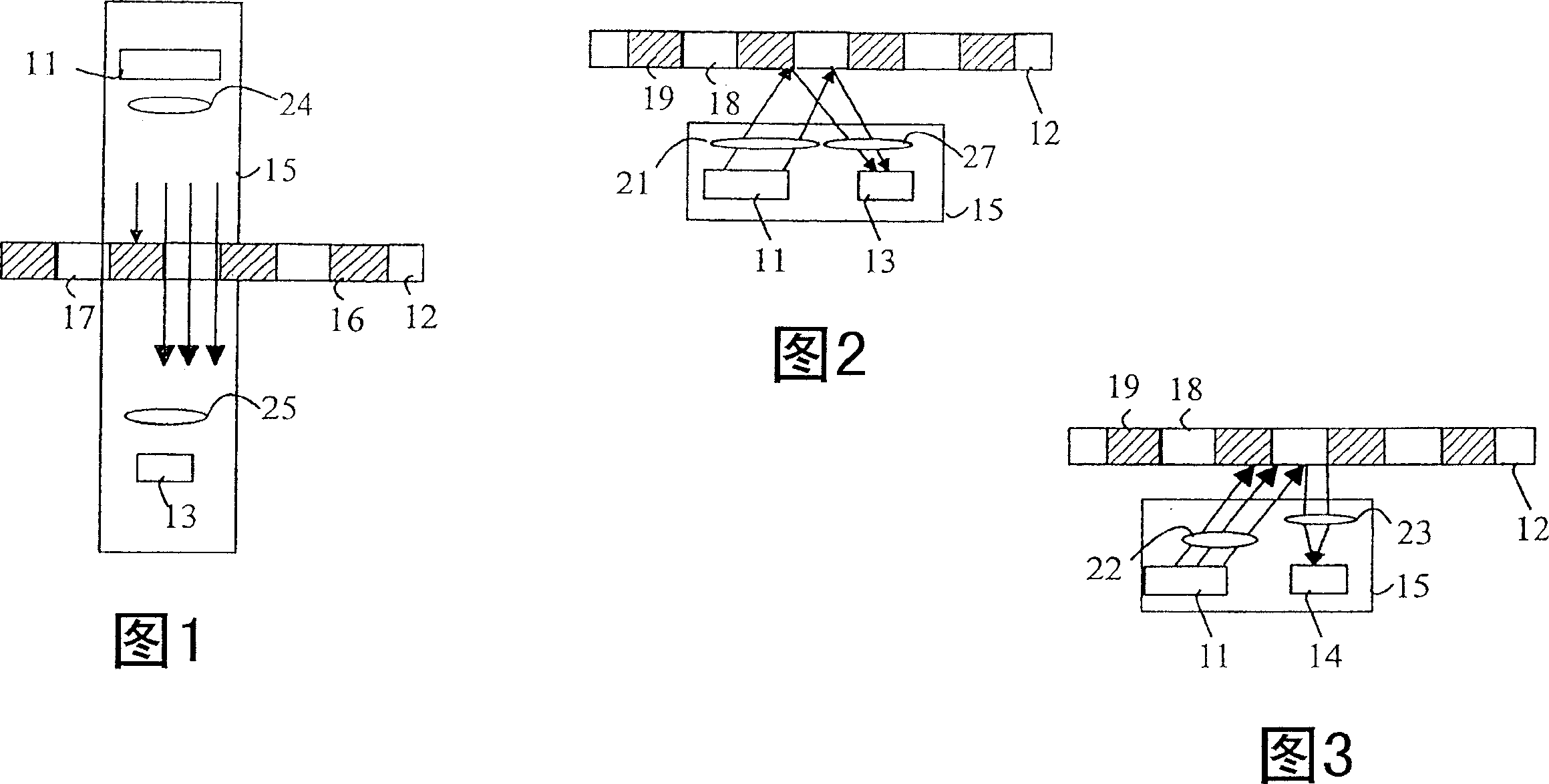
[0022] Referring now to FIGS. 1-3, some typical encoder designs are illustrated. The encoder can be divided into an emitter / detector module 15 and a code wheel or code strip. The module 15 includes a transmitter 11 which illuminates part of the code strip 12 . A detector 13 observes the illuminated code strip. Transmitters usually use LEDs as light sources. Detectors are usually based on one or more photodiodes. Figure 1 illustrates a transmissive encoder. In a transmissive encoder, the light from the emitter is collimated into a parallel beam by collimating optics such as lens 24 . Code strip 12 includes opaque stripes 16 and transparent stripes 17 . When the code strip 12 moves between the emitter 11 and the detector 13, the light beam is interrupted by the opaque stripes on the code strip. A photodiode in the detector receives the flashes of light. The resulting signal is then used to generate a logic signal that transitions between a logic 1 and a logic 0.

[0023]...


PUM


Abstract

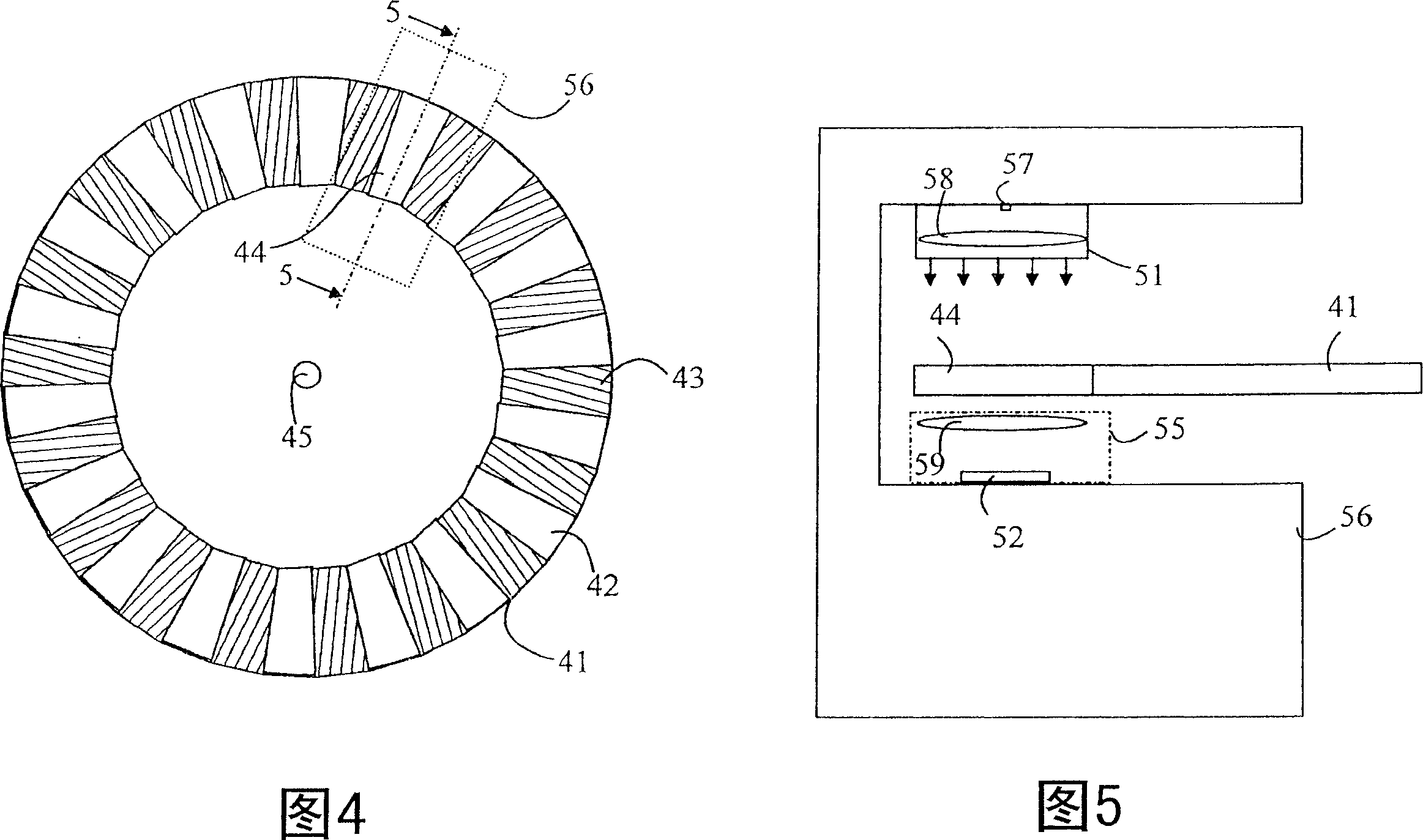
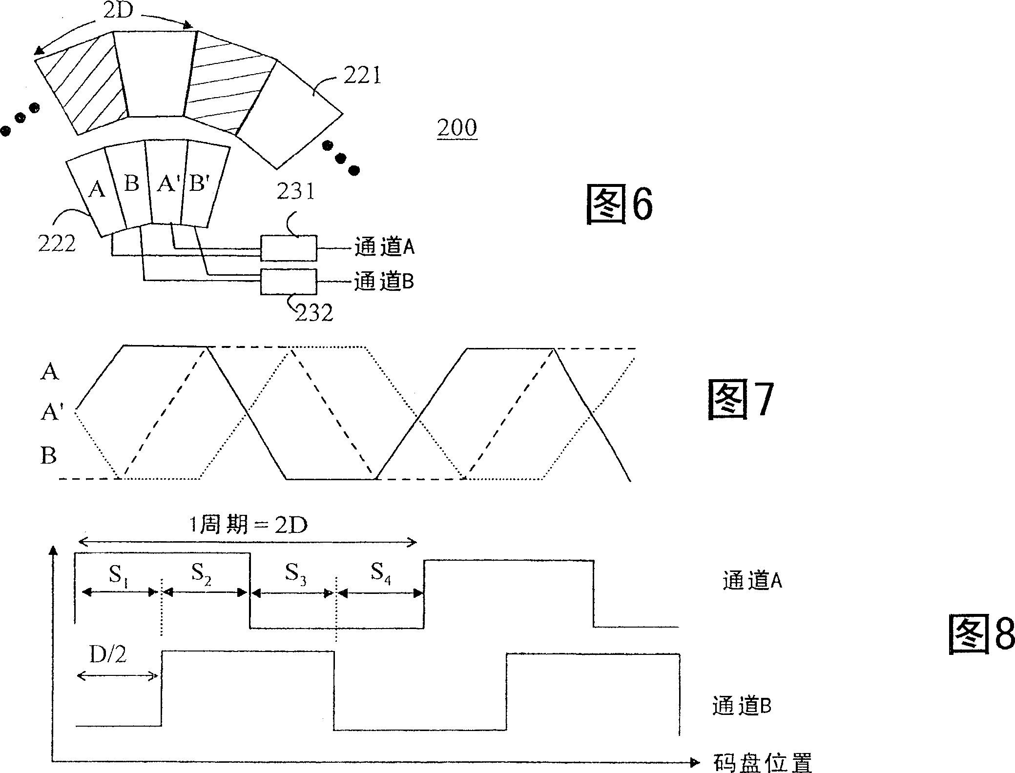
A photodiode array and an encoder utilizing the same is disclosed. The encoder includes the photodiode array, a code wheel, a light source, and an optical system. The photodiode array includes a plurality of photodiodes arranged in a ring, each photodiode includes an annular sector of the ring, each photodiode generates a signal determined by the optical radiation incident on the photodiode, the photodiode array is characterized by an array center. The code wheel includes an annular array of alternating code stripes disposed about a code wheel axis, the code wheel moving relative to the photodiode array about the code wheel axis. The light source illuminates the code wheel and the optical system forms an image of the code wheel having alternating light and dark bands on the photodiode array.

Description

technical field [0001] The present invention relates to a photodiode array and an optical encoder using the photodiode array. Background technique [0002] Encoders measure the position of components in a system relative to some predetermined reference points. Encoders are often used to provide a closed-loop feedback system to a motor or other actuator. For example, the digital signal output by a shaft encoder can represent the position of a rotating shaft relative to some known, non-moving reference position. Optical encoders employ a light source and light detectors to measure the change in position of the encoder pattern, which is carried on a code wheel or tape. [0003] In a transmissive encoder, the codewheel / codestrip consists of a series of alternating opaque and transparent strips. A light source is located on one side of the encoding pattern and a light detector is located on the other side of the encoding pattern. The light source and the light detector are fi...

Claims


Application Information

Patent Timeline
Patent Type & Authority Applications(China)
IPC IPC(8): H01L27/144G01D5/347
CPCG01D5/00G01D5/3473
Inventor 王文飞陆彻富
Owner AVAGO TECH WIRELESS IP SINGAPORE PTE
Learn More