Multiband top loaded monopole antenna

An antenna and radome technology, applied to antennas, devices that enable antennas to work in different bands at the same time, resonant antennas, etc., can solve the problems that cannot meet the goals and aesthetics of typical vehicles

Inactive Publication Date: 2007-05-30
MACOM TECH SOLUTIONS HLDG INC
View PDF0 Cites 0 Cited by
  • Summary
  • Abstract
  • Description
  • Claims
  • Application Information

AI Technical Summary

Problems solved by technology

Unfortunately, this profile falls short of the

Method used


Image

  • Multiband top loaded monopole antenna
  • Multiband top loaded monopole antenna
  • Multiband top loaded monopole antenna

Examples


Embodiment Construction

[0013] Embodiments basically relate to antenna arrangements. Although various embodiments may be described by way of example as having a certain number of elements in a particular arrangement, the embodiments are not limited thereto. For example, embodiments may include more or fewer elements, and other arrangements of these elements.

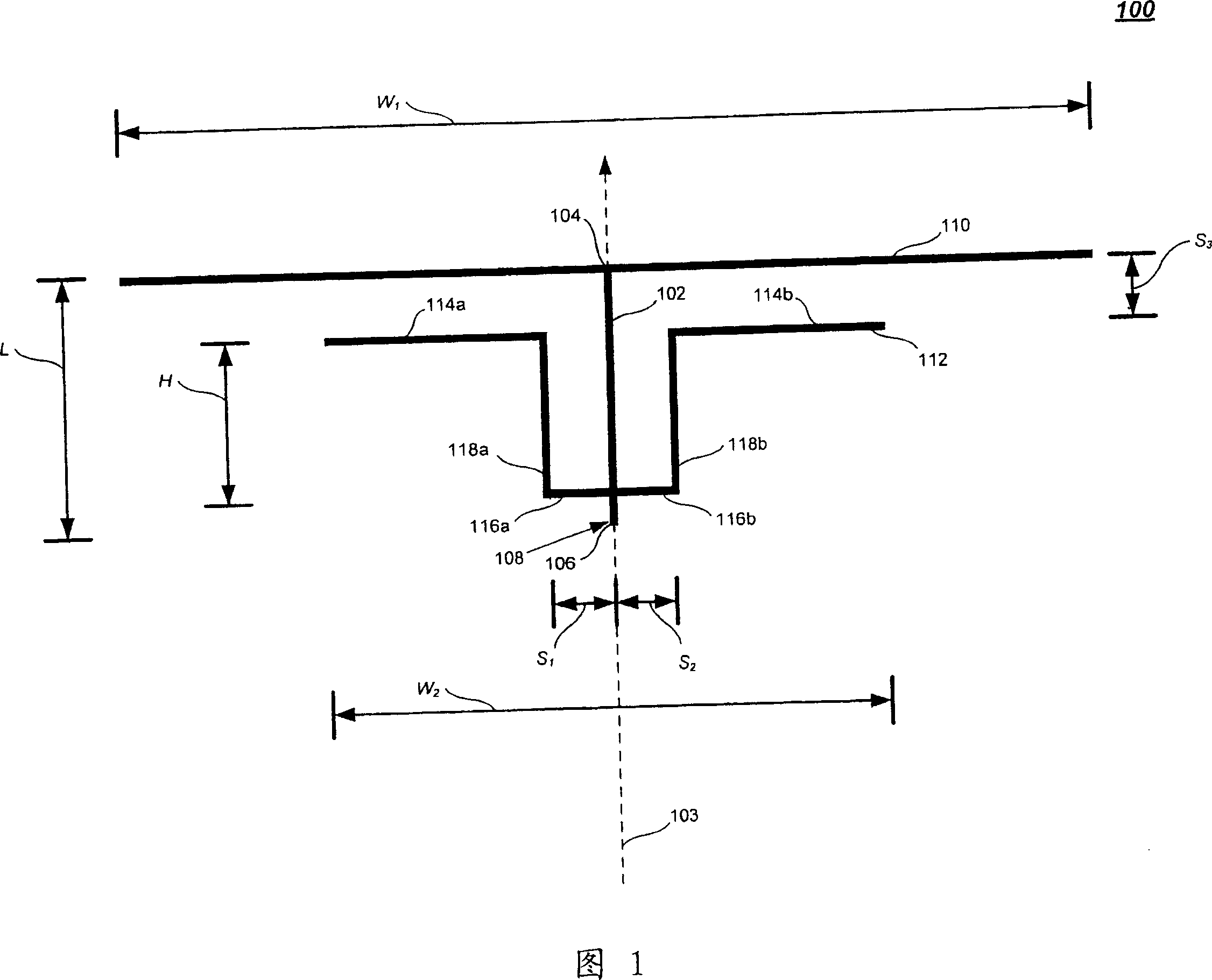
[0014] FIG. 1 is a diagram of an antenna device 100 according to an exemplary embodiment of the present invention. The device can be used to transmit and / or receive wireless signals in two or more frequency bands. As shown in FIG. 1 , the device 100 includes a monopole antenna 102 , a first payload 110 and a second payload 112 .

[0015] FIG. 1 shows a monopole antenna 102 extending substantially along an axis 103 . The axis may be substantially vertical. Additionally, the figure shows an antenna 102 having a first end 104 and a second end 106 . The distance between these ends is indicated as length L. The length may be approximately 25 t...


PUM


Abstract

An apparatus (100) includes an antenna (102) (e.g., a monopole antenna), a first load (110), and a second load (112). The antenna (102), which extends substantially along an axis (103), has a first end (104) and a second end (106). The first load (110) is coupled to the antenna at the first end (104), while the second load (112) is coupled to the antenna (102) between the first end (104) and the second end (106). Both the first and second loads (110, 112) are symmetrical with reference to the axis. The apparatus is arranged to operate in at least two frequency bands, such as the Advanced Mobile Phone System (AMPS) band from about 824 MHz to about 894 MHz and the Personal Communications Service (PCS) band from about 1850 MHz to about 1990 MHz.

Description

technical field [0001] The present invention relates to a multi-band antenna and device. Background technique [0002] It is generally desirable to reduce the size of electronic components and devices. For example, there is a need for more compact antennas for use in various wireless applications. Additionally, there is a need for antennas capable of operating in multiple frequency bands. [0003] Typical vehicular antenna systems for cellular telephones use larger antenna elements (eg, three inches or larger) to meet specific performance requirements. Larger antenna elements are usually mounted on a base and are usually surrounded by flexible vibrating reeds or rigid blades. This arrangement enables a larger profile to be created on the outer surface of the vehicle. Unfortunately, this silhouette falls short of the goals and aesthetics of typical vehicle designs. [0004] Thus, there is a need to provide antennas and antenna arrangements that are of reduced size while ...

Claims


Application Information

Patent Timeline
IPC IPC(8): H01Q5/00H01Q9/30H01Q1/32H01Q1/42H01Q5/371
Inventor 托马斯·S·劳伯纳罗伯特·希林
Owner MACOM TECH SOLUTIONS HLDG INC
Why Eureka
Try Eureka